
Communication Protocols for Laifual Drive Joint Modules: CANopen, CAN FD, EtherCAT, Modbus, BiSS-C and TAMAGAWA
Compare EtherCAT, CANopen, CAN FD, BiSS-C, and TAMAGAWA interfaces for robotic joint modules. Avoid costly late-stage bus conversions with our sizing guide.
 October 11, 2026
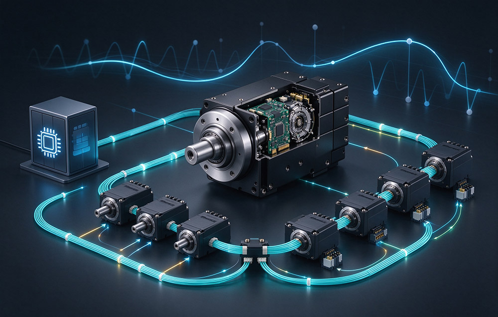
 > Communication Protocols for Laifual Drive Joint Modules: CANopen, CAN FD, EtherCAT, Modbus, BiSS-C and TAMAGAWA
A communication protocol is the interface over which a joint module exchanges position commands, feedback data, and status with the machine controller. It is the one line of a joint specification that carries no number a comparison table can rank. Torque, speed, accuracy, and mass arrive as figures that line up side by side across candidate catalog pages, so a shortlist can be ordered in minutes, while a protocol arrives as a name. On a selection sheet built to compare rated torque against outside diameter, the bus field is usually filled in last. It is sometimes left open for the commissioning stage, which is the point at which changing it costs the most.
Three causes place the decision there, and none of them is a shortage of engineering skill. Visibility comes first, because torque, speed, accuracy, and weight are quantities with units that compare directly. By contrast, a protocol is a family name whose consequences appear in cycle time, synchronization, and software structure instead of in a column of figures. Division of labor comes second, because the mechanical engineer owns size and stiffness, the electrical engineer owns supply and connectors, and the control engineer owns the bus and its real-time behavior. Selection is normally led from the mechanical side, so the protocol requirement enters near the end of the chain.
Apparent solvability comes third, because converter modules and adapter boards exist as products. Their existence suggests that a mismatch can always be repaired later, which is true in principle and expensive in practice.
From project to project, the scenario repeats. Once the structure is released and the joint sizes are fixed, the control team begins to build the system. At that point, the feedback interface of the selected joint does not match the servo drive already in the architecture, or the main bus is EtherCAT while the joint on the shortlist speaks CANopen. Common answers are a converter, a change of controller platform, or a change of joint model, and each costs more than the protocol question would have cost at selection time.
This article explains how joint-module communication protocols and encoder interfaces fit different machine architectures, what a late compatibility mismatch can cost, and which interface questions to resolve before selecting a model.
Six Protocols and Their Application Envelopes
Laifual Drive joint modules offer several communication and encoder-interface options, including CANopen, CAN FD, EtherCAT, Modbus, BiSS-C, and TAMAGAWA, depending on the product family and configuration. These interfaces serve different roles: CANopen, CAN FD, EtherCAT, and Modbus are communication protocols, while BiSS-C and TAMAGAWA are encoder interfaces. The correct choice depends on the controller architecture, servo-drive arrangement, and feedback requirements.
EtherCAT on Coordinated Multi-Axis Paths
Where several axes follow a coordinated path, the bus must deliver commands to every axis and collect feedback inside a fixed cycle. A high real-time industrial bus is the natural choice there. An EtherCAT joint module is defined less by a label on a catalog page than by whether its cycle handling, synchronization, and commissioning tooling are ready for that duty.
CANopen and CAN FD on Distributed Axes
Where axes are distributed along a structure and each carries its own drive, the lower-cost serial fieldbuses do the same work at a scale that matches the axes.
Encoder Interfaces and the Supervisory Layer
Encoder interfaces form a separate layer. When an external servo drive closes the position loop, the selected module must provide an encoder interface compatible with that drive. Modbus may be used for configuration, parameter access, or supervisory communication where supported; it should not be assumed to replace a real-time motion bus.
| Interface / Protocol | Role | Typical Application Context |
|---|---|---|
| EtherCAT | Real-time industrial Ethernet fieldbus for cyclic commands and feedback | Coordinated multi-axis motion, industrial arms, and CNC equipment, where supported by the selected module |
| CANopen | CAN-based communication protocol for commands and feedback | Distributed low-voltage axes with compatible controllers and drives |
| CAN FD | CAN-based communication protocol with a larger data payload per frame than classic CAN | Distributed control systems requiring higher data throughput, where supported |
| BiSS-C | Serial encoder interface | Feedback connection to a compatible external servo drive |
| TAMAGAWA | Encoder interface / protocol family | Feedback connection to compatible external servo-drive systems, including specified industrial configurations |
| Modbus | General-purpose industrial communication protocol | Configuration, parameter access, or supervisory communication where supported |
The Cost of a Protocol Converter
A converter is the option that looks cheapest at the moment it is proposed, and it is the one that reappears in the bill of materials. Sitting between the joint and the bus, it translates frames in both directions and adds hardware, plus an extra enclosure on a machine that has no spare volume. It also adds a delay inside the control path that no amount of downstream tuning removes. A component belonging to neither the joint nor the controller enters the design with it, so every later change on either side has to be checked against that part as well.
The other two routes cost differently rather than less. Changing the controller platform discards software assets already built around the first architecture and invalidates their verification. Changing the joint model reopens selection and repeats the envelope checks, the mounting interface review, the duty averages, and the bearing limits. In a narrow case, such as a single low-rate axis added to a legacy machine that runs no coordinated path, a converter remains defensible. That case is defined by the duty rather than by convenience.
| Recovery Route | Potential Project Impact |
|---|---|
| Converter between joint and bus | Additional hardware, enclosure space, integration effort, and possible communication delay; actual impact depends on converter and system design |
| Change of controller platform | Potential loss of existing software integration and the need to repeat verification |
| Change of joint model | Repeat selection, envelope checks, mounting-interface review, duty calculations, and bearing verification |
Drive and Encoder Integration Inside the Joint
Motor, Drive and Brake Configuration
Compatibility depends on the motor, drive, and brake configuration as well as the communication interface. Laifual Drive joint modules include a harmonic reducer, while motor, encoder, and drive arrangements can vary by product and customization plan. Some configurations integrate a servo drive; others may use a customer-selected drive or a customized board. Brake availability and integration should be confirmed for the selected model.
This approach can let a machine builder retain a previously qualified motor or drive where the chosen module configuration supports it. If a standard configuration does not meet the application requirements, Laifual Drive can review a non-standard design. The stated planning cycle is about two weeks for a proposal and about four weeks for samples, subject to project scope and confirmation. Explore our custom design service.
Bus Choice as a Catalog Decision
The low-voltage joint module family uses a 48 V DC supply. Available communication options include CANopen, CAN FD, EtherCAT, and, where specified, Modbus. The -C variant is associated with CANopen and the -E variant with EtherCAT for applicable models; suffix availability and protocol support must be checked against the current model documentation. The current low-voltage model range is L40I, L52I, L60I, L70I, L80I, L90I, L110I, L142I, L170I, and L190I. View full ratings on our DC low voltage joint modules.
Absolute Feedback and Dual-Loop Position Control
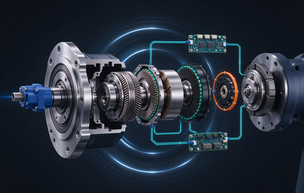
Absolute encoder behavior is model-specific. Before relying on position retention after power loss, multi-turn counting, or homing-free restart, verify the encoder specification and system behavior for the selected module and controller. Dual-loop position control also depends on the feedback signals, drive capability, and control architecture; it should not be assumed to be available on every configuration. Read our in-depth analysis on what a servo actuator is.
BiSS-C and TAMAGAWA are encoder interfaces, not general-purpose fieldbus protocols. They are available on specified high-voltage 220 V AC joint module configurations for use with compatible external servo drives. The high-voltage model range is M70, M80, M90, M110, M142, M170, and M190. Confirm the exact feedback interface, drive arrangement, and controller compatibility for each selected model.
Published Interface and Configuration Data
| Item | Published Coverage |
|---|---|
| Communication and encoder interfaces | CANopen, CAN FD, EtherCAT, and Modbus on specified configurations; BiSS-C and TAMAGAWA encoder interfaces on specified configurations |
| DC low-voltage family | 48 V DC; models L40I, L52I, L60I, L70I, L80I, L90I, L110I, L142I, L170I, and L190I. Communication options depend on model/configuration. |
| AC high-voltage family | 220 V AC; models M70, M80, M90, M110, M142, M170, and M190. BiSS-C and TAMAGAWA interfaces where specified. |
| Feedback behavior | Encoder type, multi-turn retention, and dual-loop support must be confirmed from model-level specifications |
| Joint module outside diameter | 40 mm to 190 mm across the range |
| Payload classes | Application- and model-dependent; verify module ratings |
| Protection and insulation | Check IP rating and motor insulation class in the selected model’s documentation |
| Positioning accuracy | Model- and configuration-specific; verify current product specifications |
| Design life | Depends on load spectrum, speed, lubrication, and operating conditions |
Protocol Items for the Selection Checklist
A checklist earns its keep when it is short enough to be used on every project, and these protocol items are few. Each one closes a route that would otherwise reopen during commissioning.
| Checklist Item | What to Confirm | Why It Belongs Early |
|---|---|---|
| Supply form | 48 V DC low-voltage or 220 V AC high-voltage family | Supply form narrows the relevant product and interface options |
| Bus type and real-time requirement | Confirm EtherCAT, CANopen, CAN FD, or Modbus support on the chosen configuration and match it to controller needs | Defines the command channel before the joint model is selected |
| Feedback interface | Confirm BiSS-C or TAMAGAWA compatibility where an external servo drive closes the loop | Ensures the encoder can communicate with the selected drive |
| Drive integration | Check whether the drive is integrated, supplied as a board, or provided by the customer | Links the electrical architecture to the module configuration |
| Brake | Confirm whether holding or emergency braking is required and available | Affects the configuration, wiring, and power requirements |
| Growth path | Consider whether axes may be added or the controller may change later | Helps preserve options for future system expansion |
Some systems combine 220 V AC high-voltage modules on higher-load axes with 48 V DC low-voltage modules on lighter or distributed axes. Whether this architecture is suitable depends on the required torque, bus topology, controller, installation envelope, and commissioning strategy. Do not assume that the two families share an identical mechanical interface or commissioning method; verify each model’s drawings and integration requirements. Explore our specialized integrated rotary actuators for humanoid robots.
A product range with multiple interface options can simplify system planning, but compatibility must be confirmed at the model and configuration level across our complete line of joint modules.
Protocol Selection in Practice
Protocol selection belongs to the architecture drawing, not to the commissioning log. The items that decide compatibility are the supply form, the bus and its real-time requirement, the feedback interface, the degree of drive integration, and the possibility of growth. All five can be settled in the same meeting at which the structure is laid out.
Laifual Drive’s rotary joint modules cover outside diameters from 40 mm to 190 mm across low-voltage and high-voltage families. Available interfaces include CANopen, CAN FD, EtherCAT, and Modbus on specified low-voltage configurations, and BiSS-C and TAMAGAWA encoder interfaces on specified high-voltage configurations. Select from the current catalog and model-level documentation rather than treating every interface as available on every module. Read more in our actuator robot design overview.
Choose the communication bus and encoder interface during system architecture design, before mechanical and electrical interfaces are frozen. Confirm protocol support, controller compatibility, drive integration, feedback behavior, and model-specific ratings early to reduce late-stage hardware changes, integration work, and commissioning delays.
Need Integration Advice for Fieldbus Protocols?
Our application engineering team assists with communication configuration, motion controller integration, and pinout definitions for multi-axis robotics.