
Steel Quality and Material Control in Harmonic Reducers
Discover how in-house melting, precision forging, and heat treatment dictate flexspline fatigue life, tooth accuracy, and performance in harmonic reducers.
 October 13, 2026
 > Steel Quality and Material Control in Harmonic Reducers
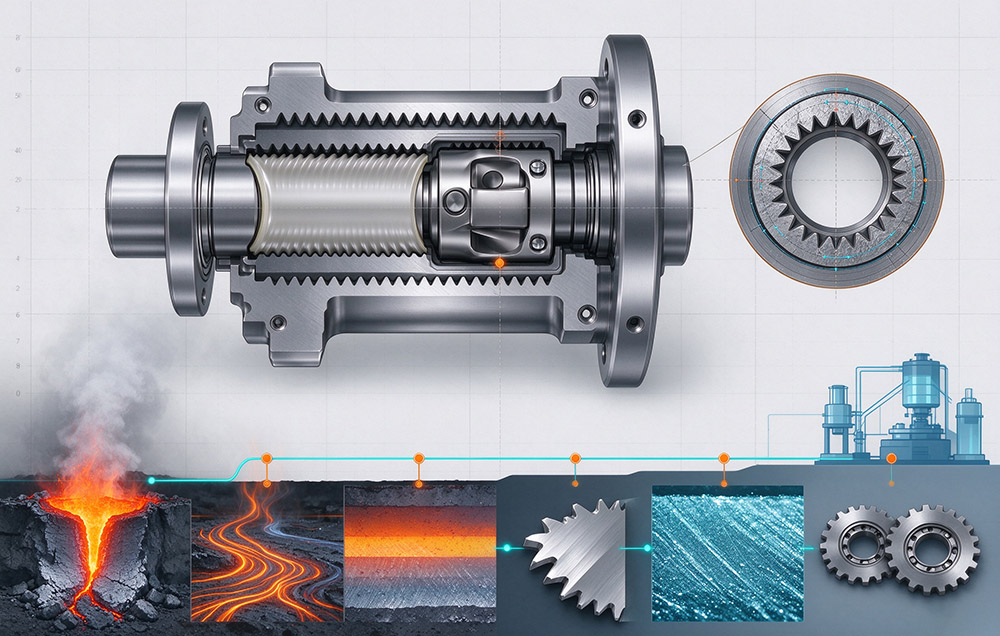
A harmonic reducer is a strain wave gear in which a thin-walled flexspline is deflected into an elliptical shape by a wave generator. Tooth engagement between the flexspline and the circular spline then advances the output by the tooth count difference. What the flexspline is made from fixes the ceiling that every later operation works beneath.
Discussion of performance in this field usually starts with tooth form geometry, cutting accuracy, and assembly sequence, and treats material as a settled premise. In practice, the order runs the other way around. Tooth form machining can correct geometric error, and heat treatment can shape a hardness gradient. Cleanliness and microstructural uniformity in the steel, however, are already decided before either operation begins.
This article sets out why material and heat treatment bound what downstream processes can achieve in a harmonic reducer. It traces how melting, forging, heat treatment, and gear cutting relate as one chain, and explains why batch consistency at the material stage is a specification requirement rather than a purchasing arrangement.
Why the Flexspline Sets the Requirement
Only the flexspline deforms continuously in service. It passes through several thousand elliptical deformation cycles per minute, and it is loaded by alternating stress at the tooth root and at the fillet of the cup. Contact stress and sliding friction act on the tooth flanks at the same time. Geometry governs how that load is distributed across the teeth. Steel governs how much of the load the wall can absorb before a crack initiates, and for how many cycles it can absorb it before the crack grows.
Four requirements follow from that duty cycle, and they pull in different directions. Table 1 lists each one with the failure mode it controls and the stage at which it can still be influenced.
| Requirement on Flexspline Steel | Failure Mode It Controls | Stage That Can Still Act on It |
|---|---|---|
| Strength and toughness together | Cracking at stress concentrations where strength is short; brittle fracture under impact where toughness is low | Forging and heat treatment, within the window set by composition |
| Microstructural uniformity | Fatigue crack initiation at inclusions, segregation, and banded structure, the main source of life scatter | Melting and forging only |
| Hardenability balanced against distortion | Distortion after heat treatment when hardenability is too high, which then caps the tooth form accuracy that can be held | Melting, with partial compensation in heat treatment and cutting |
| Cleanliness | Inclusion size and population, which act directly on fatigue life | Melting only |
The table draws a line that decides the rest of the article. Two of the four rows sit beyond the reach of any downstream operation. Tooth form machining can correct geometry but cannot remove an inclusion, and heat treatment can adjust a hardness gradient but cannot undo a segregation pattern. Both remaining rows can be tuned after the fact, within limits the steel composition has already fixed.
What External Material Supply Cannot Correct
Where the reducer manufacturer buys its steel from outside, four limitations arrive with the purchase, and none of them can be removed by incoming inspection.
Batch Consistency Across Heats
Batch consistency is the first. Different heats of the same grade differ in composition and microstructure. Those differences escape conventional incoming inspection, and they surface years later as scatter in service life across units that all passed the same acceptance test.
The Improvement Loop with the Steel Mill
The improvement loop is the second. When field failures suggest a material cause, the fix has to be negotiated with the mill. A change in melting practice must then be proposed, sampled, and run to failure in a trial batch before its effect is known. That cycle is measured in months, and it repeats for every adjustment.
Specification Access and Lot Sizes
Specification access is the third. Supply specifications and lot sizes for special steel follow the mill’s production scheduling. A low-volume specification can therefore run into minimum order quantities or delivery pressure at precisely the moment a program needs it.
Process Collaboration at Forging and Heat Treatment
Process collaboration is the fourth. Forging and heat treatment have to be designed against a specific material. Where the source is unsettled, process parameters can only be set to a compromise compatible with several sources, and that compromise is carried into every part.
Material therefore stops being a variable that can be optimized late, and becomes the starting condition for everything after it.
The Process Chain from Melt to Tooth Form
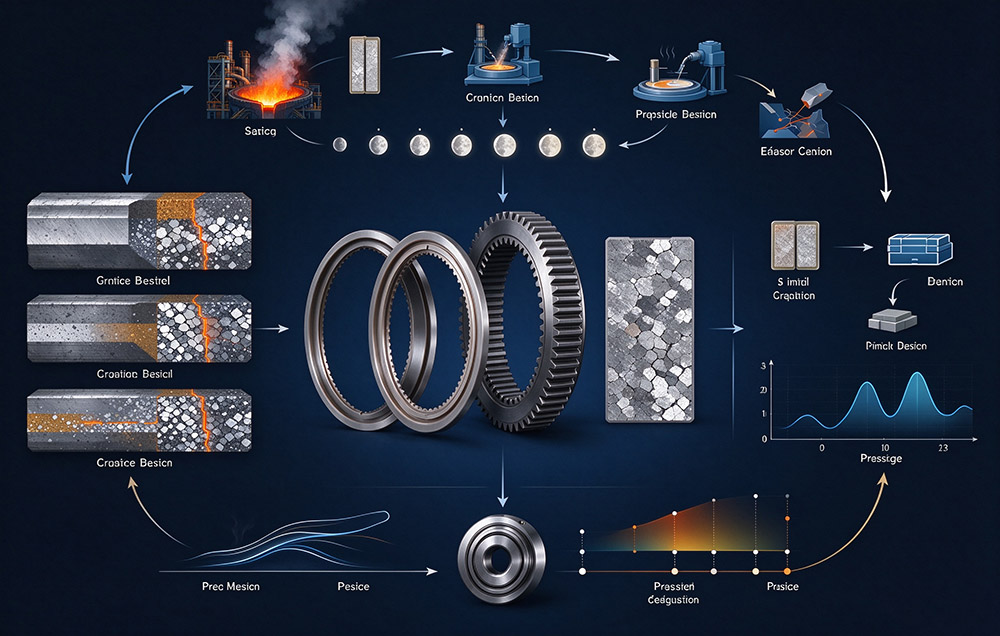
Laifual Drive builds the material stage as part of its own process route. A dedicated special steel melting line and a precision flexspline forging line were built in-house, and flexspline self-supply passed 80 percent in 2025. Table 2 reads the chain stage by stage and states what each stage fixes for the stages that follow.
| Stage | In-House Scope | What It Fixes Downstream |
|---|---|---|
| Special steel melting | Dedicated melting line | Composition window and inclusion level held as controlled process parameters |
| Flexspline precision forging | Dedicated forging line | Grain flow direction and structural density of the blank |
| Heat treatment | Own plant covering quenching, tempering, austempering, and vacuum treatment | Distortion behavior and the hardness gradient in the wall |
| Gear cutting | Self-developed process, core part machining time reduced from two to three hours to less than 15 minutes | Tooth form accuracy at a cycle time that can be repeated |
| Core parts | Flexspline, circular spline, and cross roller bearing produced internally | Mutual tolerance balance between the three mating parts |
The stages act on one another. Melting determines the inclusion level that forging can only redistribute, never remove. Forging determines the grain flow that the heat treatment response then acts on. Heat treatment determines how much distortion the blank carries, which sets the stock allowance gear cutting must remove, and that removal sets the residual stress left in the finished wall. That wall, with the tooth form, then sets torsional stiffness and the shape of the hysteresis curve under reversing load.
At the forging stage, the two are treated as one design problem. A heat treatment process that combines super-strength steel forging with normalizing and annealing is covered by an in-house patent position. That patent is the formal expression of designing forging and the treatment that follows as a single step.
The practical meaning of in-house heat treatment is the same. A distortion signature measured after quenching can be answered by a change in the cutting program at the next station, inside the same batch cycle. The correction stays inside the plant, with no specification change traveling to an outside supplier. Holding melting, forging, and heat treatment under one system shortens the feedback path further, because an adjustment can be validated from the melting parameter through to the finished unit.
How Material Control Reaches the Product Data
Material investment only counts once it appears in figures a design engineer can use. Table 3 collects the specifications the chain above has to deliver, with the process contribution behind each one.
| Parameter | Specification | Note |
|---|---|---|
| Positioning accuracy | ±15 arcseconds | Output side |
| Design life | 10,000–15,000 hours | Depends on average load torque and input speed |
| Backlash, by series | ≤60, ≤30, and ≤20 arcseconds | Population value per series |
| delta profile load capacity | 15 to 30 percent higher | Against the conventional double circular arc profile |
| delta profile temperature rise | 8 to 10 °C lower | Same reference |
| delta profile pitting-exposed contact area | More than 30 percent smaller | Same reference |
| delta profile continuous running life | Above 15,000 hours | Same reference |
| Rated torque | Permissible continuous load torque at a rated input speed of 2,000 rpm | Catalog definition |
| Flexspline self-supply | Above 80 percent in 2025 | Dedicated melting and forging lines |
No row in that table is the output of a single operation. Load capacity depends on the tooth form and on material strength acting together. Temperature rise depends on friction behavior in the tooth form and on the match between material and heat treatment. Fatigue life depends on cleanliness, microstructural uniformity, hardness gradient, and residual stress jointly. That is why the gear tooth profile and the steel beneath it have to be specified as one problem.
The delta profile, developed as a multi-segment continuously variable curvature arc on the basis of a double circular arc form, is the clearest case. Laifual Drive can maintain that geometry only when the material state and the treatment response move with it. A profile specification that depends on several suppliers is met on the prototype and lost in volume.
Material control also reaches the envelope. The strain wave gear series covers size 3 to size 58, reduction ratios of 30:1–160:1, and outside diameters of 13–246 mm. The FB series serves different mounting interfaces from the same material base. Where a load case or envelope falls outside the standard range, our custom design service specifies the part around the interface instead.
Batch Consistency as a Specification
Every figure in Table 3 describes a production population and holds across a shipment, so the scatter inside that population matters as much as the nominal value. Material control stops being a capability claim at that point and becomes a constraint on specification. A strength range demonstrated on one prototype becomes a specification only when it repeats across a batch, and repeatability belongs to the material at least as much as to the machining.
The mechanism is arithmetic. Each process stage contributes its own distribution of variation to the finished part: cutting parameters vary with tool wear and thermal state, heat treatment with furnace position and load, assembly with preload. Each distribution can sit inside its own tolerance and still stack into a wider band in the finished product.
When melting and forging come under the same system as treatment and cutting, the number of independent distributions feeding the flexspline falls, and the width of the combined band narrows with it. Backlash, lost motion, and starting torque follow the same pattern, all quoted as values that hold across a shipment.
That reduction is what makes it possible to quote ±15 arcseconds of positioning accuracy or a design life of 10,000–15,000 hours as catalog figures rather than laboratory results.
Laifual Drive maintains dedicated fatigue testing covering fatigue fracture, tooth flank wear, and cross roller bearing wear failure, and each mode maps to a different link in the chain. Fracture maps to the forged flexspline wall and its structure, flank wear to the tooth form and the surface left by cutting, and bearing wear to internal bearing production and preload. Running the test inside the organization that runs the process shortens the path from a failed specimen to a corrected parameter, because the test record and the process record come from the same batch.
Material Control and Specification Confidence
Material is the input that no downstream process can recover, so the ceiling on a harmonic reducer’s performance is set at the melt. Cleanliness and microstructural uniformity are fixed at melting and forging, hardness gradient and distortion by heat treatment, and only geometry can still be corrected at the cutting stage. In-house melting and forging, with flexspline self-supply above 80 percent in 2025, keep those early decisions inside a single process system instead of spreading them across a supplier boundary.
That arrangement appears in the data. Positioning accuracy of ±15 arcseconds and a design life of 10,000–15,000 hours depend on the material state and the process response being adjustable together. So do the delta profile results: 15 to 30 percent higher load capacity, 8 to 10 °C lower temperature rise, more than 30 percent smaller pitting-exposed contact area, and continuous running life above 15,000 hours.
For a design engineer, the usable conclusion is that material and heat treatment should be treated as specification inputs rather than as background assumptions. When a load case demands more capacity or a longer life than the standard range provides, the tractable route is to raise the requirement from the material and treatment end of the chain. Strength, distortion, and fatigue resistance are decided there, so the change should be confirmed on a built unit as well as on paper.
Need Custom Metallurgy or Flexspline Fatigue Data?
Connect with our materials engineering laboratory for detailed fatigue test curves, specialized alloy formulations, and custom actuator specifications.