
Harmonic Reducers for Medical Imaging Equipment: Selection and Performance Requirements
Explore motion control requirements for CT gantries and patient tables. Learn how low noise, high smoothness, and delta tooth profiles optimize imaging axes.
 October 17, 2026
 > Harmonic Reducers for Medical Imaging Equipment: Selection and Performance Requirements
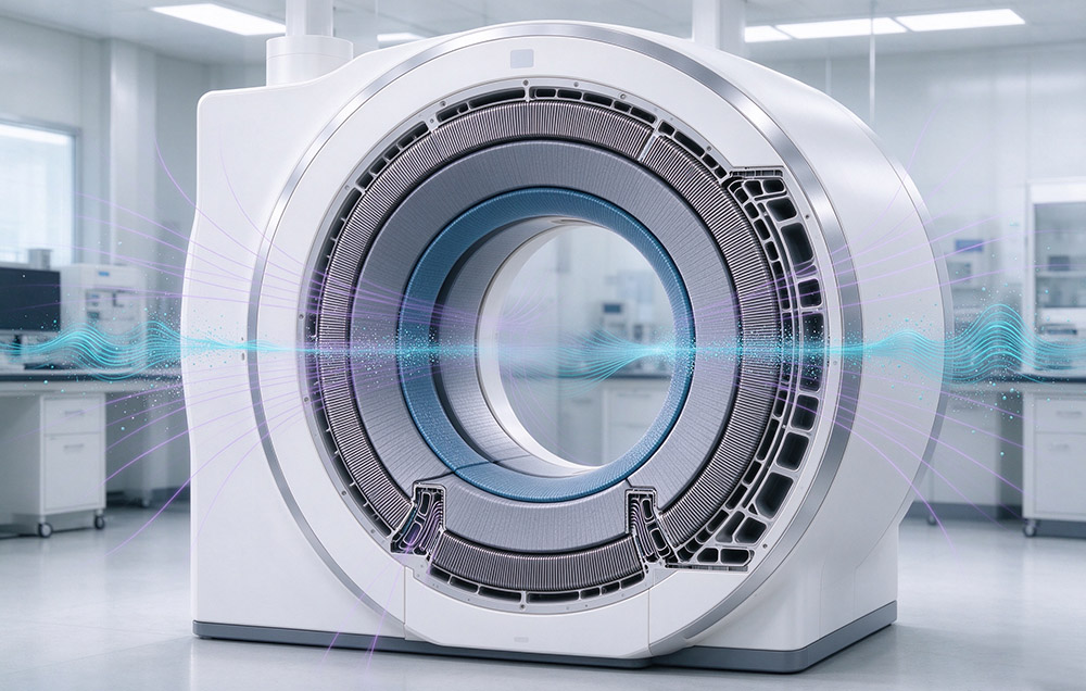
A harmonic reducer converts the high-speed, low-torque output of a servo motor into the low-speed, high-torque rotation that positions a patient table or turns a CT gantry. In imaging equipment, a torque curve does not describe the whole requirement: airborne noise in the scan room, vibration at the detector, and smoothness at low output speed all count. So does accuracy retained over years of continuous duty, and absolute position held across a power interruption without a new calibration cycle.
Those requirements arrive as one motion quality specification, not as separate line items. A scan taken while the patient moves is a lost scan, so noise and vibration are clinical questions before they are comfort questions. A detector that drifts a few arcseconds between calibrations displaces the reconstructed geometry.
This article explains the motion-control requirements of medical imaging applications, the operating conditions behind each specification, and the selection, installation, and maintenance considerations that follow. Laifual Drive offers strain wave gear reducers from size 3 to size 58, with outside diameters ranging from 13 mm to 246 mm.
Why Noise and Vibration Are Specification Items in Imaging Rooms
In a CT or MR suite, the rotating mass that produces the image is the same mass the patient hears and feels. Acoustic behavior of the gear stage therefore sits inside the design envelope. An uncomfortable patient moves. Movement during acquisition degrades image quality directly, and vibration reaching the detector assembly or the reference structure shifts the reconstructed geometry.
Low noise is therefore a base performance index, specified with the same discipline as torque. It cannot be separated from the rest of the specification, because tooth impact and load handover generate noise and vibration together.
How Strain Wave Gearing Produces Smooth, Quiet Motion
Strain wave gearing engages a large share of the tooth pairs in mesh at the same time, so load is spread across those pairs and each tooth carries little load. Torque passes through the mesh as a continuous process. Output motion is smooth and quiet at low output speed, where the contact pattern stays regular.
Published third-party test data for the delta tooth profile—a multi-segment, variable-curvature arc profile derived from the conventional double circular arc profile—reports approximately 40% lower vibration amplitude and an 8–10 dB(A) reduction in noise. These figures should be understood in the context of the test conditions and reference design.
Lost motion, motion uniformity, and temperature are the remaining requirements. Angular positioning converts backlash at the output directly into imaging error. An axis that reverses direction does not return to the same output position for the same encoder command. Multi-tooth preloaded engagement holds that lost motion small. Backlash is quoted by series at up to 60, 30, or 20 arcseconds, with positioning accuracy of ±15 arcseconds.
A CT gantry rotates at constant speed for a whole acquisition, so velocity ripple appears as geometric distortion. Continuous duty means temperature rise acts on accuracy, through noise and through thermal deformation. Temperature rise falls by 8 to 10 °C with the delta tooth profile, which supports continuous running life beyond 15,000 hours.
Components and Their Roles on an Imaging Axis
Flexspline, Circular Spline and Wave Generator
A strain wave set has three working elements. The flexspline is a thin-walled externally toothed cup that deforms under the wave generator. Inside it sits the circular spline, the internally toothed ring it engages, with two teeth more than the flexspline. The wave generator is the elliptical bearing assembly that imposes the deformation. The layout gives a high reduction ratio coaxially, and the strain wave gear series covers size 3 through 58 at ratios of 30:1–160:1.
Output Bearing and Machine Interface
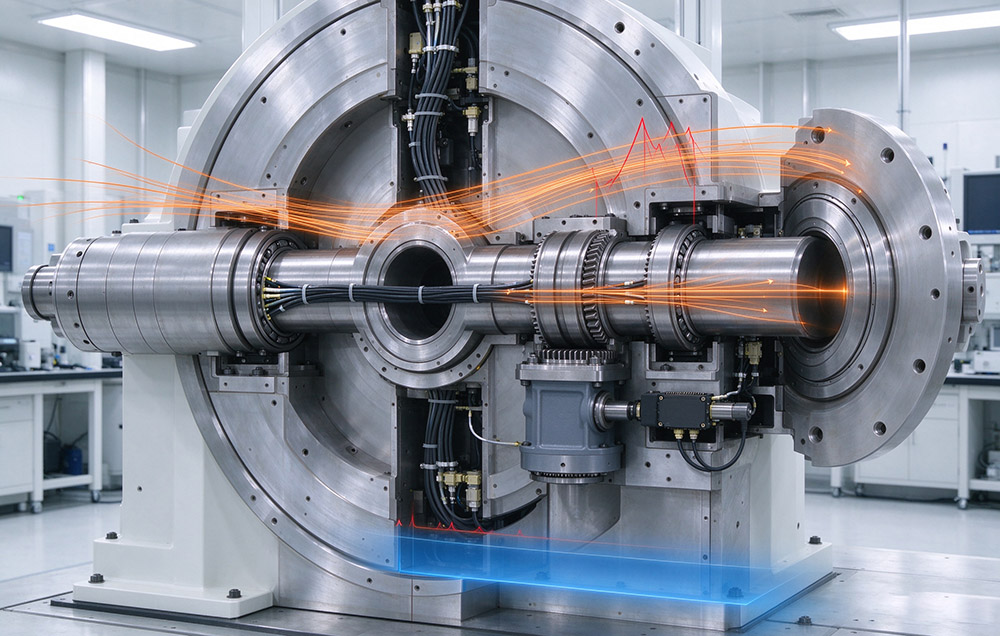
An imaging axis also requires an output bearing and a suitable machine interface. Unit-type reducers incorporate a cross roller bearing designed to support combined radial, axial, and moment loads, potentially eliminating the need for a separate output bearing. Hat-type FHT designs provide a hollow shaft for cable routing. For powered axes, joint modules integrate a reducer, servo motor, absolute encoder, and servo drive in one housing; torque sensing is available where specified.
Parameter Definitions and Operating Points
Torque and Speed Operating Points
Every quantity below carries an operating point that must be stated with the number. Rated torque is the permissible continuous load torque at a rated input speed of 2,000 rpm, so a frame adequate at rated speed loses continuous capacity as the axis runs faster. Average load torque Tav is the torque over a complete duty cycle, and it sets the frame size, which must allow at least Tav. Average input speed Ni av and maximum input speed Ni max are compared against the catalog range for the chosen ratio and frame. Where the reducer carries its own output bearing, the check adds moment load, bearing life, and static safety factor.
Accuracy, Backlash and Design Life
Accuracy rests on measurements that are often confused: backlash is the lost motion at the output when the input is reversed with no load, and it converts directly into imaging error. Hysteresis is the output position difference between loading and unloading, while repeatability is the spread of positions returned under one command. Design life of 10,000–15,000 hours is quoted for the reducer, not the grease fill or the seals.
| Parameter | Definition | Operating Point or Value |
|---|---|---|
| Rated torque | Permissible continuous load torque | Defined at 2,000 rpm input |
| Average load torque Tav | Torque averaged over a duty cycle | At or below the permissible average load torque |
| Ni av and Ni max | Average and maximum input speed | Within the catalog range for ratio and frame |
| Positioning accuracy | Output position error | ±15 arcseconds |
| Backlash | Lost motion at the output on reversal | Up to 60, 30, or 20 arcseconds by series |
| Design life | Rated service life of the reducer | 10,000–15,000 hours |
Technical Data for Imaging Drive Selection
Laifual Drive’s strain wave gear range for medical imaging includes the FSS, FSF, FSN, FSG, FHT, FHG, FHD, FHN, FBS-U, FBS-C, and Mini series, covering sizes 3 through 58. The FSN lightweight series is designed to reduce mass while maintaining the rated torque, stiffness, and transmission accuracy specified for the relevant model.
Load capacity rises by 15 percent to 30 percent with the delta tooth profile. The same profile reduces the area affected by tooth flank fatigue pitting by more than 30 percent, and it supports continuous running life beyond 15,000 hours. For powered axes, the joint module range covers 40 mm to 190 mm outer diameter, with 40 mm near reducer size 8 and 170 mm near size 40.
| Element | Specified Range | Engineering Note |
|---|---|---|
| Reducer range | Size 3 to size 58, 13–246 mm outer diameter, 30:1–160:1 | Eleven frame families |
| Backlash and accuracy | Up to 60, 30, or 20 arcseconds, ±15 arcseconds | Accuracy class chosen against the error budget |
| Delta tooth profile | Load capacity plus 15 to 30 percent, temperature rise 8 to 10 °C lower, running life beyond 15,000 hours | Pitting contact area down by more than 30 percent |
| Joint module envelope | 40 mm to 190 mm | Joint-module models and dimensions depend on the selected series |
| Module protection and drive | IP67, 48 V DC low-voltage or 220 V AC high-voltage | DC models: L40I, L52I, L60I, L70I, L80I, L90I, L110I, L142I, L170I, and L190I; AC models: M70, M80, M90, M110, M142, M170, and M190 |
| Encoder, bus, and insulation | Absolute encoder; DC low-voltage (48 V): CANopen, CAN FD, EtherCAT, and Modbus; AC high-voltage (220 V): BiSS-C and TAMAGAWA | Communication protocols depend on the voltage series; verify encoder and protocol configuration for the selected model |
The absolute encoder lets a module-based axis satisfy the position hold requirement. It retains position and multi-turn counts when power is removed, so the axis resumes from a known position instead of running a homing sequence. A scanner needs no manual recalibration after a supply failure. On a reducer without an encoder, backlash and lost motion are properties of the machined and assembled gear set. They do not drift with duty cycle, as harmonic drives in medical technology sets out from the application side.
Selection Procedure for an Imaging Axis
1
Build the axis table: continuous torque, peak torque during acceleration, maximum output speed, angular resolution required by the reconstruction, and reflected inertia of the load and everything beyond the axis.
2
Compute the average load torque Tav over the duty cycle and confirm it is at or below the permissible average load torque of the candidate frame. Frame size follows from Tav, not from the peak value.
3
Compare Ni av and Ni max for the cycle against the catalog range of the selected ratio and frame, since rated torque is defined at 2,000 rpm input.
4
Fix the accuracy class against the error budget: backlash, positioning accuracy, and repeatability against the angular error the reconstruction tolerates.
5
Check the output bearing on unit-type frames: maximum moment load, bearing life, and static safety factor at the worst posture, including the overhung detector mass.
6
Check the thermal case. An imaging suite runs continuously, so the reducer must sit inside the operating point the frame was rated for.
7
Confirm the position hold and interface requirement. An encoder-based axis resumes from a retained absolute position after a power loss, and hollow shaft routing must clear the cables crossing the axis.
Installation, Sealing, and Maintenance Practice
Installation follows the interface data of the frame and the sealing data of the reducer. The FHT-I, FHT-II, and FHT-V configurations specify oil seal and groove dimensions. Assembly requires the input fixed end to be sealed against the circular spline and flexspline, the output end against the circular spline, and the flexspline cavity to be filled with grease. Three checks are worth making on site.
Mounting Verification
Confirm the mounting pattern and flange tolerance against the drawing before the reducer is bolted into a load path that carries the detector.
Thermal Envelope
Keep the duty cycle inside the envelope the selection established, because a reducer run above its thermal operating point loses life before it loses accuracy.
Baseline Commissioning
Record the protocol version, encoder parameters, and measured backlash and repeatability at commissioning, so the next service interval has a baseline.
Maintenance turns on the difference between design life and wear items: the grease fill and the oil seals determine when the unit is serviced, not the rated life of the gear set. Backlash, hysteresis, and repeatability are the acceptance values to measure at each interval: they drive imaging performance and can be checked without dismantling the axis. Batch-to-batch consistency in those values comes from the manufacturing sequence: the tooth form is cut by controlled precision gear shaping technology and the rings are heat treated in-house before grinding. A replacement reducer therefore reproduces the accuracy of the original, without forcing the axis to be recalibrated.
Specifying Reducers for Imaging Axes
Imaging axes buy their performance in units that a torque rating alone does not express. Sound pressure in the scan room, vibration at the detector, and smoothness at low output speed all carry weight. So does accuracy that stays inside the same band after years of continuous duty.
Specifying such an axis fixes the accuracy class first, then checks average load torque and input speed against the selected frame. It then verifies moment load, bearing life, and static safety factor wherever the reducer carries its own output bearing. Laifual Drive supplies that requirement as components from size 3 to size 58 and as joint modules from 40 mm to 190 mm. A gantry axis and a surgical arm axis can therefore be specified on one parameter set.
The design measure that protects the clinical result is to write backlash, lost motion, and repeatability into the axis drawing as acceptance values at commissioning. Those are the quantities a scanner reproduces every working day.
Design a Low-Vibration Imaging Axis
Contact our medical motion engineering team for acoustic test reports, custom hollow-shaft configurations, and 3D CAD support.