
Sealing Design Requirements for IP67 Joint Modules
Discover engineering requirements for IP67 robotic joint modules: rotary seal interfaces, FHT groove geometry, grease cavity control, and washdown testing.
 October 25, 2026
 > Sealing Design Requirements for IP67 Joint Modules
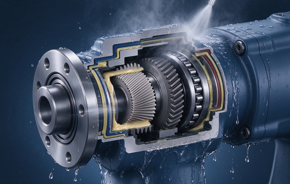
A joint module is an integrated actuator that can combine a servo motor, strain wave gear set, absolute encoder, servo drive, and brake in one housing; a torque sensor is included where specified. Depending on the design, the output assembly may incorporate a cross-roller bearing. Integration consolidates multiple components within one enclosure and can simplify system-level sealing for the machine builder.
IP67 is often treated as a feature that can be added late in a design, as a rubber ring pressed into a groove on the output flange. That reading does not survive the requirement. A rotating axis has to keep fluid out at surfaces that move relative to each other. It must hold a defined grease fill across a design life of 10,000–15,000 hours, and keep doing both while the motor raises the internal temperature and the shaft deflects under load. Four layers of work produce that result: the sealing interfaces in the structure, material compatibility with the fluid actually present, the assembly process, and a verification sequence long enough to cover wear.
This article follows the order a design review settles these requirements for an IP67 joint module: the static and rotary interfaces, the sealing points on the module boundary, groove geometry, and grease fill. Then come the assembly variables that decide whether two units come out equally tight, and verification for washdown and cutting fluid duty, the regime that dominates machine tool applications.
Margin for error is small: the grease film that carries the tooth load is also the first barrier against ingress. Fluid admitted past the seal emulsifies the grease at the flexspline and circular spline contact. Running torque and temperature rise follow, and positioning accuracy of ±15 arcseconds degrades before an external leak becomes visible.
Static Sealing and Rotary Sealing Are Different Engineering Problems
Static Sealing Interfaces
Static sealing acts between parts that do not move relative to each other: an end cover on a housing, a connector body in a cavity wall, a bearing retainer on a flange. It turns on the flatness of the mating faces and the compression the seal element receives when the joint closes. Tightening torque then has to repeat around the bolt circle. Flatness and a compression that repeats at every bolt make the static seal a settled element of the design.
Rotary Sealing at the Output Flange
Rotary sealing acts where parts move relative to each other, most critically between the output flange and the surrounding housing. This is the weakest point in the protection system, and the practical dividing line between a module that carries a protection grade on its label and one that holds that grade in service.
Blocking fluid requires the lip to conform closely to the shaft surface, without pressing so hard that friction raises running torque and temperature. It must also tolerate the wear of long rotation, while following small radial excursions of the shaft as load passes through the output bearing. High speed, high load, and frequent reversal amplify those effects. Excitation described in vibration control in harmonic reducers also reaches the lip, because orbital motion of the output under load is what the lip has to follow.
For a machine builder comparing two modules, the informative question is how the rotary interface at the output is built, not the protection grade alone.
The Four Sealing Interfaces on a Joint Module Boundary
Four interfaces make up the protection boundary, each with its own assembly requirement. At the input fixed end, it has to be closed against both the circular spline and the flexspline, which are stationary but differ in stiffness and in the way they are clamped. At the output side, a rotary interface separates the rotating flange from the fixed housing. Housing joint, cover fasteners, and the connector or cable entry gather into the fourth interface, the largest non-metallic boundary of an integrated module.
| Sealing Interface | Relative Motion | Seal Arrangement | Requirement at Assembly |
|---|---|---|---|
| Input fixed end to circular spline | None, static | Face seal in a machined groove | Uniform compression around the full bolt circle |
| Input fixed end to flexspline | None, static | Face or radial seal at the flexspline rim | Contact load low enough not to distort the flexible rim |
| Output side to circular spline | Rotary | Lip seal with groove geometry specified per family | Concentricity of the seal counterface to the output axis |
| Housing joint and connector interface | None, static | Gasket or O-ring, sealed cable entry | Flatness, sealed fasteners, controlled tightening sequence |
Sealing geometry is never left as a free dimension on the drawing. Oil seal and groove dimensions are specified per reducer family, FHT-I, FHT-II, or FHT-V. Which seal variant applies therefore follows from the strain wave gear series that carries a given size and ratio. The achievable protection level is set by the rotary interface, and the other three decide whether it holds from unit to unit.
How Seal and Groove Geometry Is Specified
Groove depth and width set the compression the lip receives, and compression balances two failure modes. Too little and the lip does not stay in contact around its whole circumference, so fluid passes at the first sign of eccentricity or internal pressure. Too much and friction rises, which raises running torque, temperature, and lip wear. Because one groove has to serve both limits, its dimensions are fixed per family, with no adjustment per application. Mating parts are machined so the counterface stays inside its concentricity and finish limits.
Counterface quality deserves as much attention as the groove. Eccentricity of the counterface to the output axis opens and closes the lip once per revolution, pumping fluid along the shaft and wearing the lip unevenly. Finish matters in both directions: too rough abrades the lip, while too smooth prevents the thin lubricant film that keeps it from running dry. On the output side, this counterface belongs to the same precision component group as the bearing race, which is why sealing and cross roller bearing design are settled together.
| Item | Specification Basis |
|---|---|
| Sealing arrangement | Oil seal and groove dimensions specified per family, FHT-I, FHT-II, or FHT-V |
| Grease fill | Flexspline cavity filled to a defined quantity during assembly |
| Rated torque | Permissible continuous load torque at a rated input speed of 2,000 rpm |
| Backlash | 60, 30, or 20 arcseconds or less, by series |
| Positioning accuracy | ±15 arcseconds |
| Design life | 10,000–15,000 hours under specified conditions |
| Ingress protection | IP67, dust tight and protected against temporary immersion |
Grease Fill, Material Compatibility and Assembly Control
Grease Fill and Cavity Venting
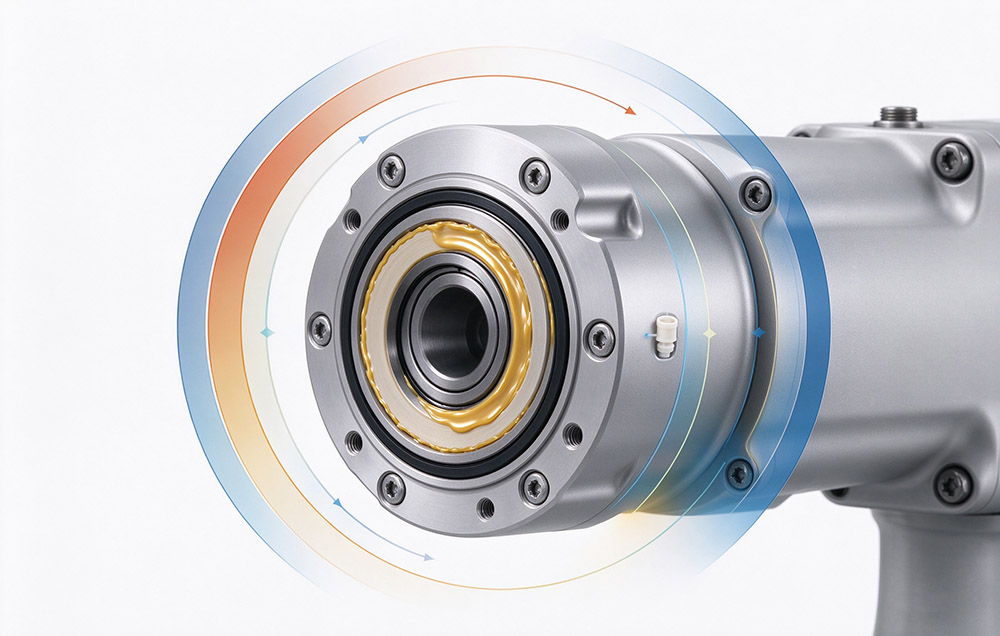
At assembly, the flexspline cavity is filled with a defined quantity of grease, and that quantity is a sealing parameter as much as a lubrication one. Contact starved at the tooth flanks raises temperature and shortens life, while an overfilled cavity churns and heats. Heating and cooling of a sealed cavity can draw a pressure difference across the lip seal. Measured and recorded, a defined fill keeps the mesh lubricated without loading the seal from the inside.
Material Compatibility with the Working Fluid
Material compatibility is the variable most often left out of a sealing specification. Cutting fluid is not water. It contains emulsifiers, rust inhibitors, and extreme pressure additives, and formulations differ between brands and machines. A seal compound that swells, hardens, or cracks after prolonged contact loses its protection irreversibly. Housing surface treatment, cable jacket, and the potting compound around the drive electronics carry the same risk.
Black oxide is the oxidation treatment applied to T-type joints and selected precision bearings. It forms a dense oxide film that raises resistance to rust, but relies on an oil film for full effect. Sealing data should therefore be specified against the fluids the machine actually uses, and confirmed by immersion and aging tests.
Assembly Variables That Set Repeatability
Assembly decides how much of the design intent reaches the product, because the same drawing and the same batch of parts can produce units at different protection levels. The variables that matter are few and can all be controlled.
Each seal is checked for installed posture, and seated without twisting.
Grease quantity is controlled in the flexspline cavity and in the bearing.
Cover and interface bolts follow a set tightening sequence and torque.
Any pressure difference between the cavity and the outside air is handled during assembly.
Treating those four steps as parameters instead of craft is what makes a protection level repeatable across a production run. That matters most on an integrated, high-torque joint module that carries the gear, the motor, and the electronics inside one enclosure.
Verifying Sealing Under Motion, Fluid and Time
A standard ingress test answers one question: whether a sample passes a stated condition. It says little about spray duration, fluid chemistry, rotation, or long duty. Three additions close that gap. A dynamic test runs the module while fluid is applied, so the rotary lip is loaded in its working state instead of at rest. Thermal cycling gets its own test: the module temperature is raised and lowered with the cavity closed, exercising seal compression and the pressure difference across the lip.
Long-term immersion then leaves the seal material, the housing finish, and the cable jacket in the real medium. Compatibility with cutting fluid can fail after months even when it passed in a week. Where a module reverses frequently, as in integrated rotary actuators for humanoid robots, the test cycle should include that reversal, not rotation in one direction only.
| Verification Stage | What It Establishes | Applied To |
|---|---|---|
| Standard ingress test | Whether the enclosure passes the stated condition | Complete module |
| Dynamic test under rotation | Whether the rotary interface holds while the axis turns | Output lip seal, cable entry |
| Thermal cycling with the cavity closed | Whether compression and grease behavior survive temperature change | Seal interfaces, grease fill |
| Long-term immersion in the actual medium | Whether seal, finish, and jacket stay compatible with the fluid | Seal material, housing finish, cable jacket |
Laifual Drive has also run an IP67-rated joint module in a public exhibition demonstration involving water immersion. Any claim about performance under load should be tied to the documented test conditions.
Specifying Sealing and Assembly
A sealing specification for an IP67 joint module should read as a set of instructions instead of a grade. It should name the four interfaces on the module boundary and the seal variant that closes each one. Grease type and quantity placed in the flexspline cavity belong there too, along with the tightening torque and sequence for the cover and interface bolts. Fluids the module will meet should be named as well, with the tests that prove compatibility, since a water test alone does not cover emulsified cutting fluid.
Sealing is decided in four layers, so a change in any one of them reopens the verification. A different grease, a different fluid, or a different tightening torque changes what the lip sees, and the protection level has to be re-established. Laifual Drive produces the flexspline, the circular spline, and the cross-roller bearing in-house, and operates its own heat treatment. Seal counterface and the bearing seat are therefore held within one process chain, which is the basis for specifying sealing, assembly torque, and grease fill as parameters. Verified that way, protective performance becomes an outcome of the design and assembly record instead of a claim on a label.
Rated torque at 2,000 rpm input and backlash of 60 to 20 arcseconds or less stay valid in the environment where the machine actually runs. So do positioning accuracy of ±15 arcseconds and a design life of 10,000–15,000 hours.
Configure Your IP67 Joint Module Protection
Consult our sealing specialists for customized elastomer selection, FHT seal groove models, and coolant compatibility test reports for severe CNC and robotics environments.