Why Critical Processes Stay In-House: Process Control in Harmonic Reducer Manufacturing
Explore full-chain harmonic reducer manufacturing at Laifual Drive. Learn how in-house forging, heat treatment, and gear cutting ensure batch consistency.
 October 03, 2026
 > Resources > Why Critical Processes Stay In-House: Process Control in Harmonic Reducer Manufacturing
 A harmonic reducer is a strain wave gear in which a flexspline with two fewer teeth than the circular spline is deformed by an elliptical wave generator. That tooth engagement advances the output by the tooth count difference and produces a high reduction ratio in a single stage. Its mechanism is compact and well understood. The manufacturing problem behind it is another matter.
Output repeatability is fixed by three things: the geometry of the tooth profile, the metallurgical state of the flexspline wall, and the runout and stiffness of the cross roller bearing carrying the external load. Each of those is the output of a process, and each process leaves a signature that survives into the finished unit. Positioning accuracy of ±15 arc seconds and design life of 10,000 to 15,000 hours are process results before they are catalog figures.
This article examines process scope in harmonic reducer manufacturing at Laifual Drive. The questions are which operations are performed in-house, how that scope affects batch consistency and delivery response, and which interfaces remain deliberately open to customer-supplied components. Explore our full product catalog or browse all harmonic reducers for details.
The Problem Is the Distribution, Not the Average
Subcontracting an operation lowers fixed investment and shortens the time needed to reach volume. For a bracket, a cover or a housing, that trade is usually correct and there is no reason to bring the work inside. A strain wave gear behaves differently, for four structural reasons.
Process Visibility and the Process Record
Process visibility is the first. A purchasing company receives an inspection report, while the process record stays inside the supplier. When a batch drifts, the cause has to be reconstructed across two organizations. Which furnace cycle or which tool wear state produced the result cannot be answered from incoming inspection data alone.
Parameter Drift Across Machines
Parameter drift is the second. Performed on different machines at different times, the same operation carries different thermal, kinematic and clamping conditions. Any single variation may sit inside its tolerance, but the sum of them widens the distribution of the finished product.
Queue Position and Delivery Rhythm
Queue position is the third. A subcontractor’s capacity is shared across many customers. Priority during a busy quarter follows commercial terms, so the delivery rhythm of the buying company sits partly outside its own control.
The Improvement Loop Across Operations
The improvement loop is the fourth. Raising output accuracy usually requires several operations to move together. These include the stock allowance left for cutting and the distortion produced by quenching, the tooth cutting parameters and the flexspline wall thickness, and the bearing preload and the assembly sequence. Where some of those operations belong to another company, coordinated adjustment becomes negotiation, and the time needed to close an improvement grows with the number of parties involved.
For precision transmission products, manufacturing consistency is the product performance. Consistency is available only to the organization that can observe and adjust the whole process as one system.
Process Scope in Harmonic Reducer Manufacturing
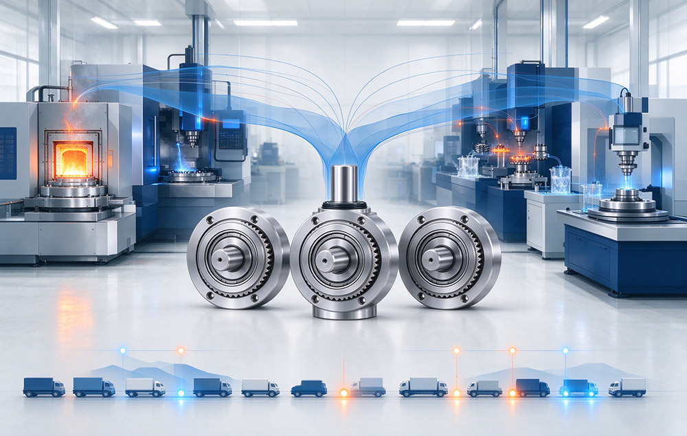
Laifual Drive runs a full-chain route from raw material to finished unit. The table below lists the operations covered internally and what that coverage contributes to batch consistency.
| Process stage | In-house scope | Effect on batch consistency |
|---|---|---|
| Material | Dedicated special steel melting and precision flexspline forging lines; flexspline self-supply above 80 percent in 2025 | Chemistry and forging grain flow stay under one specification for every batch |
| Heat treatment | Own heat treatment plant with multiple equipment types, covering quenching, tempering, austempering and vacuum treatment | Distortion behavior is characterized once and then held, instead of varying between suppliers |
| Gear cutting | Self-developed gear cutting process; core part machining time reduced from two to three hours to under 15 minutes | A stable cycle time allows identical cutting conditions to be repeated across a batch |
| Core parts | Flexspline, circular spline and cross roller bearing produced internally | Tolerances of the three mating parts can be balanced against each other |
| Module level | Capability extends to torque motors, encoders and drives for joint modules | Interface and calibration parameters are set where the reducer itself is manufactured |
| Verification | Dedicated fatigue testing covering fatigue fracture, tooth flank wear and bearing wear failure | A failure mode can be traced back to a process parameter inside the same system |
Each row removes a boundary that would otherwise sit between a measured result and the process that produced it.
How the Process Chain Sets Consistency
Read the process scope table as a chain, with each link feeding the next. Heat treatment distortion determines how much stock the gear cutting operation has to remove. Stock removal determines the residual stress distribution in the flexspline wall. That wall, together with the tooth profile, determines torsional stiffness and the shape of the hysteresis curve under reversing load.
Because quenching, tempering, austempering and vacuum treatment sit under the same quality system as cutting and assembly, process parameters can be adjusted jointly instead of being accepted one operation at a time. This is the practical meaning of in-house heat treatment, and a furnace on site is only part of it. A distortion signature measured after quenching can be answered by a change in the cutting program at the next station, within the same batch cycle.
Backlash shows the effect in numbers. Laifual Drive specifies backlash by series at ≤60, ≤30 and ≤20 arc seconds. Such a figure describes a production population, with no selected sample behind it, and the same holds for positioning accuracy, lost motion and starting torque. Reducing the number of independent process owners reduces the number of independent distributions that have to be stacked, so the scatter a customer sees across a shipment narrows with it.
Precision manufacturing at Laifual Drive makes the same argument from the drawing side. Developed on the basis of a five-tooth design, the δ tooth profile is a multi-segment continuously variable curvature arc. It raises load capacity by 15 to 30 percent, lowers temperature rise by 8 to 10 °C and reduces the pitting-exposed contact area by more than 30 percent.
Those gains are only manufacturable when the tool path, the material state and the heat treatment response can be moved together. When a profile specification depends on three suppliers, it is met on the prototype and lost in volume. This chain produces a range that covers the strain wave gear series from size 3 to size 58. It spans reduction ratios of 30:1 to 160:1 and outside diameters of 13 mm to 246 mm, including hollow shaft units and the FB series family built for different mounting interfaces.
Fatigue Testing as a Process Instrument
A declared design life is only meaningful when the failure mode behind it is understood. Laifual Drive maintains dedicated fatigue testing capability and tests across the full life cycle for fatigue fracture, tooth flank wear and cross roller bearing wear failure.
Each mode maps to a different part of the process chain. Fracture points to the flexspline wall and its forged structure, flank wear to the tooth profile and the surface left by cutting and finishing, and bearing wear to internal bearing production and preload. Running the test inside the same organization that runs the process shortens the path from a failed specimen to a corrected parameter. Both engineers work from the same batch records.
Numbers attached to the δ profile show what that loop produces. Continuous running life exceeds 15,000 hours, load capacity increases by 15 to 30 percent, temperature rise falls by 8 to 10 °C and the pitting-exposed contact area shrinks by more than 30 percent. For a machine builder, the value of those figures lies in their repeatability. They hold across the units arriving on the assembly line, one after another, over years of production.
How Process Scope Affects Delivery Response
Delivery performance follows from the same scope. When the critical operations are internal, capacity allocation and scheduling become engineering decisions, settled in-house instead of through commercial negotiation. Process changes requested by a customer can be attempted without a third party re-quoting them first. Non-standard design work has been turned around in about two weeks, and sample delivery in about four weeks. That response pattern depends on the material, heat treatment, cutting and assembly steps being addressable by one planning group. Behind those figures sits a production structure described further under full-chain production.
For a machine builder, the practical consequence is a shorter loop between a request and a physical part to test. A deviation found on a prototype can be fed back as a process adjustment, with the specification left intact. That revision can then be produced instead of merely agreed.
Which Interfaces Stay Open
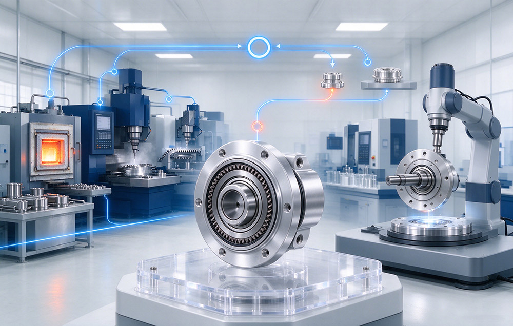
Full-chain production does not mean a closed configuration. On joint modules, Laifual Drive keeps the harmonic reducer as the self-developed core fitted across the range. Motor selection is offered as an open option with custom matching. Drive selection covers either an integrated driver and encoder board or a customer-supplied solution, and the brake is selected as required. Engineering collaboration is equally open: joint research platforms are maintained with Chongqing University, Zhejiang University of Technology and Huazhong University of Science and Technology, and R&D centers operate in several cities.
Here the distinction is between process control and configuration freedom. Control over the critical operations is what makes batch consistency possible, while openness at the interface is what lets those consistent units fit a machine the customer already designs. Where the standard range does not cover the envelope or the load case, the custom design service defines bearings and structural parts around the interface instead of expecting the machine to meet a catalog shape.
Technical Data
The table below collects the parameters that the process scope described above ultimately has to deliver.
| Parameter | Specification | Note |
|---|---|---|
| Positioning accuracy | ±15 arc seconds | Output side, absolute position |
| Design life | 10,000 to 15,000 hours | Depends on average load torque and input speed |
| Backlash, by series | ≤60, ≤30 and ≤20 arc seconds | Stated as a population value per series |
| Reduction ratios | 30:1 to 160:1 | Single stage |
| Size and envelope | size 3 to size 58; 13 mm to 246 mm outside diameter | Several hundred SKUs |
| Rated torque | Permissible continuous load torque at a rated input speed of 2000 r/min | Catalog definition |
| δ profile, load capacity | 15 to 30 percent higher | Against the conventional double circular arc profile |
| δ profile, temperature rise | 8 to 10 °C lower | Same reference |
| δ profile, pitting-exposed contact area | More than 30 percent smaller | Same reference |
| δ profile, continuous running life | Above 15,000 hours | Same reference |
| Flexspline self-supply | Above 80 percent in 2025 | Special steel melting and precision forging lines |
| Core part machining time | Under 15 minutes | Self-developed gear cutting process, reduced from two to three hours |
| Plant and engineering | 47,000 square meters; R&D team of more than 100 people | Joint research platforms with universities |
| Cumulative deliveries | More than 1,000,000 harmonic reducers | Company listed as 03952.HK |
What Process Control Means for Batch Consistency
Process scope in harmonic reducer manufacturing is a decision about where variation is allowed to enter. Bringing material melting and forging, heat treatment, gear cutting, core part production and fatigue testing under one system reduces the number of independent distributions inside a production batch.
That reduction appears later as repeatable positioning accuracy, stable backlash and a design life that holds across a shipment, unit after unit. Delivery response follows the same structure, because capacity allocation and process changes can be decided internally, within a planning horizon instead of a commercial negotiation between separate owners. Some interfaces stay open by design, including motor, drive and brake selection on joint modules, so that consistently produced units fit a machine the customer already designs.