Matching Joints to Every Axis of a Multi-Joint Robot
Master robot joint selection for humanoid and cobot arms. Learn to match strain wave gears and integrated modules to specific axis loads and frame sizes.
 September 25, 2026

 > Matching Joints to Every Axis of a Multi-Joint Robot
 The wrist of a humanoid platform and its waist rotation axis see different loads, inertia, and space allowances. That spread routinely exceeds a factor of ten. Robot joint selection therefore means matching each axis to a structural series and a frame size, not repeating one part number down the bill of materials.
Laifual Drive develops and manufactures strain wave gears and integrated joint modules across a broad and continuous size range. Harmonic reducers run from size 3 to 58, with outside diameters from 13 mm to 246 mm and ratios from 30:1 to 160:1. Joint modules cover 40 mm to 190 mm without a gap. Criteria for assigning a unit to an axis, and a procedure applied axis by axis, follow below.
Robot Joint Selection Starts with the Load Distribution Across Axes
A humanoid robot may carry more than 20 joints; a collaborative arm usually 6 or 7. Distal joints move the least mass. Proximal joints carry the whole chain, payload, and reflected inertia of everything downstream, so the highest torque and precision requirements rarely fall on the same axis. Mapping where each axis sits on that spectrum is the work of humanoid robot joint design.
Frame size follows no single trend either. Wrist and finger axes run fast under light load, where a compact, light unit cuts the inertia the elbow and shoulder must accelerate. Waist and base axes run slowly under the largest torque and moment load. There output bearing stiffness and resistance to tilt matter more than mass.
One model across that range fails at one end or the other. A large unit at the wrist adds mass and inertia that raise the required torque at every proximal axis, while a small unit at the base runs hot and loses life.
The duty cycle organizes the exercise. Continuous torque, average speed, peak torque duration, and the direction of the dominant external load determine which acceptance check governs. Ratio and frame size fix the motor speed and torque the drive must deliver.
What an Integrated Joint Module Contains
An integrated joint module replaces a chain of separately sourced parts. Explore our complete product categories for modular solutions.
| Subassembly | Function in the joint |
|---|---|
| Servo motor | Delivers input torque and speed; insulation class F, rated to 155 °C |
| Strain wave gear | Provides the reduction ratio, the output torque capacity, and the torsional stiffness |
| Absolute encoder | Reports position and the multi-turn count after a power loss, for dual loop control |
| Servo driver | Closes the position and speed loops internally on the low voltage range |
| Torque sensor | Measures output torque for force control and collision detection |
| Cross roller bearing | Carries axial, radial, and tilting load directly at the output flange |
Flexspline, Circular Spline, and Wave Generator
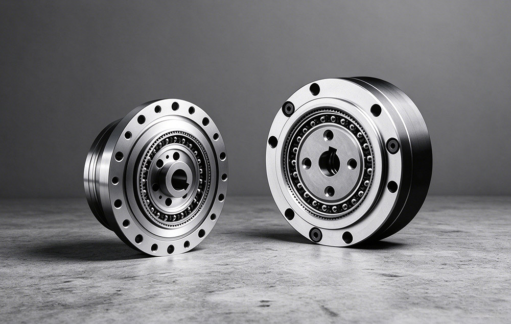
The flexspline is the thin walled cup or hat carrying external teeth, and it deforms elastically into the circular spline and sets rated torque and torsional stiffness. A rigid internal gear, the circular spline normally carries two more teeth than the flexspline, and the two tooth counts fix the reduction ratio. At two diametrically opposed zones, the wave generator deflects the flexspline into mesh, and its stiffness contributes to lost motion.
Output Bearing and Moment Load Path
The output bearing is the fourth element and often decides whether a joint design closes. Where the output flange takes an external moment load directly, an integrated cross roller bearing carries it without a second bearing pair. Laifual Drive produces flexsplines, circular splines, and cross roller bearings in-house. In-house supply keeps the strain wave gear series size sequence continuous rather than limited to a few stocked sizes.
How Rated Torque, Average Load Torque, and Backlash Are Defined
Each parameter below carries its reference condition, since a torque figure without its input speed reference cannot be compared across suppliers.
| Parameter | Definition and reference condition |
|---|---|
| Rated torque | Permissible continuous load torque at a rated input speed of 2000 r/min |
| Permissible average load torque | Upper limit for the time-weighted average load torque over the duty cycle |
| Average input speed Ni av | Time-weighted average of the input speed; checked against the permissible average |
| Maximum input speed Ni max | Highest momentary input speed permitted; checked against the duty cycle peak |
| Positioning accuracy | ±15 arc seconds for the product family |
| Backlash | Graded by series at ≤60, ≤30, or ≤20 arc seconds |
| Design life | 10,000 to 15,000 hours, series and duty dependent |
| Moment load | Tilting load at the output flange; a separate check for unit type joints |
Rated Torque and the Governing Average Load Torque
Rated torque is defined at 2000 r/min input: the torque the unit transmits continuously at that speed without exceeding its thermal limit. Permissible continuous torque is higher below that speed and lower above it. For an axis that runs continuously, rated torque does not govern. The controlling quantity is the permissible average load torque, checked against the time-weighted average of the load torque over the cycle.
Bearing Capacity as a Separate Criterion
Bearing capacity is a separate criterion from gear capacity. A unit with an integrated cross roller bearing must also pass a maximum moment load check, a bearing life calculation, and a static safety factor check. Backlash grade follows the axis accuracy requirement rather than the ratio.
Delta Tooth Profile Effect on Capacity and Life
The δ tooth profile is the second selection dimension: the conventional double circular arc optimized into a multi-segment, continuous variable curvature arc. It raises load capacity by 15% to 30% and reduces temperature rise by 8 to 10 °C. That same profile reduces the contact area affected by tooth flank fatigue pitting by more than 30%, and it sustains running-in life beyond 15,000 hours.
Technical Data: Size Coverage and Axis Class Matching
| Product group | Size coverage | Reduction ratio | Note |
|---|---|---|---|
| Harmonic reducers, full range | Size 3 to 58; outside diameter 13 mm to 246 mm | 30:1 to 160:1 | Several hundred SKUs across cup, hat, double circular spline, ultra thin, and high torque families |
| FSN lightweight series | Within the standard size range | Matches the standard unit | About 30% lower mass at equal rated torque, stiffness, and transmission accuracy |
| DC low voltage joint modules | Outside diameter 40 mm to 190 mm; L40I, L52I, L60I, L70I, L80I, L90I, L110I, L142I, L170I, L190I | Configurable | 48 V DC supply with built-in servo driver; supports CANopen, CAN FD, EtherCAT and Modbus communication protocols |
| AC high voltage joint modules | M70, M80D, M90D, M110D, M142D, M170D, M190 | Configurable | 220 V AC supply, compact design, high precision, large hollow-shaft structure; supports BiSS-C and TAMAGAWA communication protocols |
Joint modules cover payload classes from 3 kg to 20 kg and hold IP67 protection. Absolute encoders retain position and the multi-turn count through a power loss, supporting dual loop control. DC low voltage joint modules suit humanoid limbs, collaborative robots, and distributed control architectures, while AC high voltage joint modules with a large hollow shaft serve high power industrial arms and CNC equipment.
| Axis class | Representative positions | Dominant requirement | Product approach |
|---|---|---|---|
| Light distal | Wrist, fingers, vicinity of the end effector | Low mass, small volume, fast response | Lightweight design and ultra thin structure; FSN series at about 30% lower mass |
| Mid chain, medium load | Elbow, shoulder | Torque and stiffness in a limited envelope | High torque series with increased torque capacity |
| Base, heavy load | Waist, base rotation axis | High load capacity, high stiffness, resistance to tilting | Large frame sizes paired with a high stiffness cross roller bearing |
| Hollow routing | Joints that pass cables, air lines, or vacuum lines | Large through bore at the axis center | Hat type large hollow design; lightweight hollow series for compact volume |
Matching Each Axis to a Frame Size, Step by Step
Selection is carried out per axis. Steps 1 to 4 size the unit, and steps 5 to 7 confirm it survives the duty cycle and meets the accuracy requirement.
- List every axis and its requirements. For each joint, record the outside diameter limit, the mass budget, the maximum and average output torque and speed, and the required positioning accuracy. Add whether a hollow bore is needed for routing, the mounting orientation, and the required backlash grade. Count drives the total, not any single unit price. Review joint count and cost scaling before the list is fixed.
- Establish load torque and speed for each axis. Compute output load torque from the gravity term of link and payload mass, the inertia and angular acceleration term, and the external process force. Convert output side values to input side values through the reduction ratio. Then derive the average and maximum input speed the cycle requires.
- Compare the average load torque with the permissible average load torque. Calculate the time-weighted average load torque Tav over the full cycle, including holding periods. That value must stay at or below the permissible average load torque of the candidate unit. A unit that passes on peak torque but fails this check runs hot and loses life.
- Select the frame size and the structural series. Take the smallest frame size that satisfies step 3 with margin. Then the series follows the physical requirement: a lightweight or ultra thin unit covers a distal axis, and the integrated high torque robot joint modules family covers the mid chain. Hat type hollow units serve joints where cables pass through the center. Large frames suit the waist and base rotation.
- Verify the speed checks, Ni av and Ni max. Confirm that the average input speed Ni av stays within the permissible average. The maximum input speed Ni max must stay within the permissible maximum. Both are limits in their own right: an axis acceptable on average is still unacceptable if its transient peaks exceed the maximum.
- Verify the moment load and the bearing capacity. For a unit type with an integrated cross roller bearing, check the maximum moment load at the output flange. Calculate bearing life for the actual moment and axial load profile, and confirm the static safety factor against the worst case. This check usually governs at the waist and base axes.
- Fix the backlash grade and confirm the precision budget. Select the grade from the positioning accuracy and repeatability required by the axis: ≤60, ≤30, or ≤20 arc seconds. Family positioning accuracy is ±15 arc seconds, so a precision axis should not take the widest grade merely because it shares a frame size with a heavy axis.
Two errors recur: over-unification standardizes every joint on one model to simplify procurement, leaving light positions overweight and heavy positions short of capacity. The second error is peak-only selection, reading rated torque and ignoring temperature rise, life, and smoothness.
Sealing, Mounting, and Drive Interface Notes
Mechanical integration determines whether the calculated life is reached.
- The input fixed end and the seal between the circular spline or flexspline and the housing are specified together. Groove dimensions differ between FHT-I, FHT-II, and FHT-V arrangements.
- The output side needs its own seal against the circular spline, and the flexspline cavity must be filled with the specified grease before closure.
- Mounting orientation assumed in the bearing calculation must match the build drawing, since it changes the moment load path and grease distribution.
- The 48 V DC units come in CANopen and EtherCAT versions, and BiSS-C, TAMAGAWA, CANopen, CAN FD, EtherCAT, and Modbus cover the common controller set. Black oxide treatment is available on applicable T-type joint configurations and selected precision bearings, depending on the product specification.
Specifying Each Axis from Its Own Load Data
Multi-joint robot design begins with the load distribution along the kinematic chain. Distal wrist and finger axes move little mass at high speed, while the waist and base rotation axis carry the full chain, the payload, and the reflected inertia at the highest torque.
That map fixes the technical sequence. Check the time-weighted average load torque Tav against the permissible average before selecting the frame size and structural series, then confirm the moment load, bearing capacity, and backlash grade against the accuracy requirement.
Sizing every axis from its own duty cycle data, before any procurement standardization, keeps light positions light and heavy positions within capacity. That sequence matters because a unit that passes on peak torque but fails the Tav check runs hot and loses life. Every axis is therefore specified on its own measured load and speed data rather than on a shared part number. For further assistance configuring your systems, contact Laifual Drive engineering support.