How do strain wave gears achieve zero backlash?
Understand how strain wave gears achieve zero backlash with unique elastic structure. Learn the principle and benefits of zero backlash harmonic reducers for precision transmission.
![]() April 10, 2026
April 10, 2026
When looking at how strain wave gears achieve zero backlash, the answer lies in continuous elastic deformation and massive tooth engagement. Instead of just one or two rigid teeth touching, an elliptical wave generator forces a flexible metal gear to expand and engage with a rigid outer ring.
This outward radial pressure allows about 30 percent of the gear teeth to mesh simultaneously. This large contact area and preloaded engagement completely eliminate the mechanical clearance and play found in traditional gearboxes.
The Battle Against Mechanical Play
If you design positioning systems, rotary tables, or robotic joints, you know that mechanical play is the absolute enemy of accuracy. Backlash is defined as that tiny amount of clearance between mating gear teeth.
In a standard gear setup, you simply have to accept a certain amount of backlash. Without that microscopic gap, the gears would bind up, overheat, and fail to retain their lubrication film.
However, when you are engineering a system that requires extreme precision, that tiny gap becomes a massive headache. Lost motion translates directly to positioning errors at the end of a robotic arm. It causes chattering when reversing directions and makes tuning your servo control loops incredibly frustrating.
Why Traditional Gears Fall Short
This eternal compromise between tight meshing and mechanical binding is exactly why engineers turn to strain wave gears. Also commonly known by the generic term harmonic reducers, this technology takes a completely different mechanical approach to motion transfer. By relying on flexibility rather than total rigidity, it breaks the standard rules of gear design.
To fully understand how these drives eliminate backlash while providing massive gear reduction, we need to take a deep dive into the mechanical architecture. We must look at how their internal components interact under the hood.
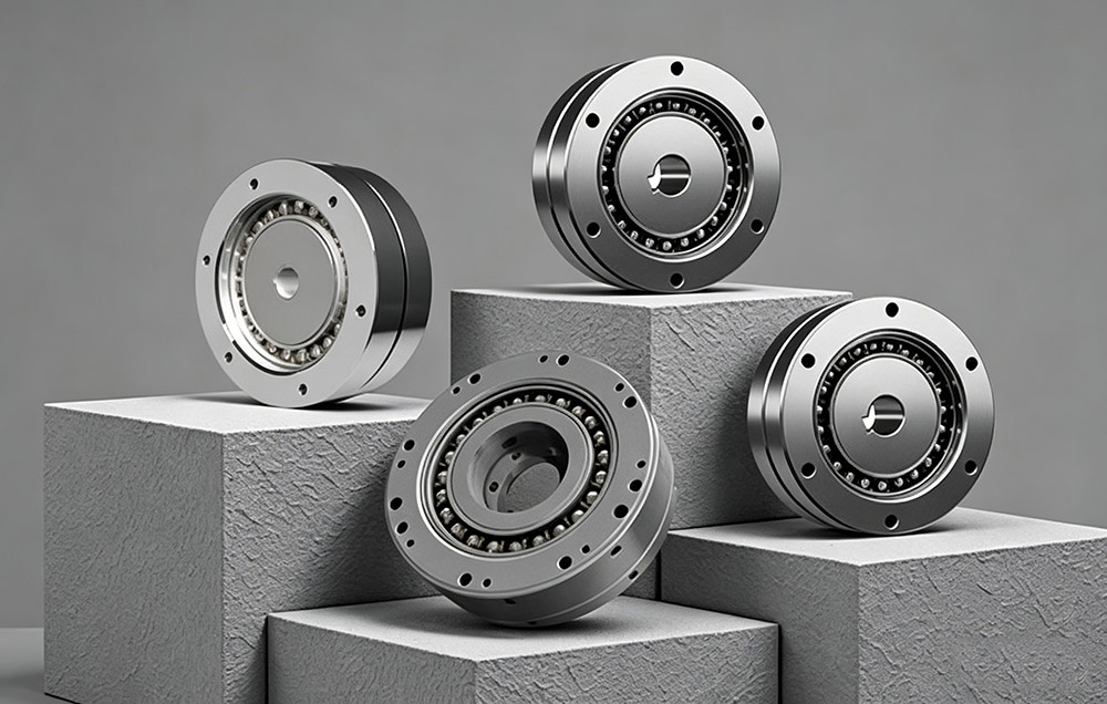
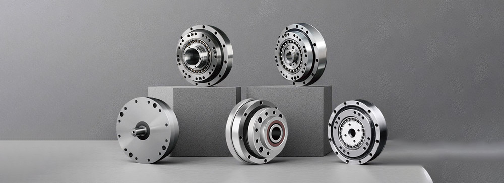
Deconstructing the Three Core Components
If you look inside a traditional planetary gearbox, you will find a complex arrangement of a central sun gear, multiple planet gears, a carrier, and an outer ring gear. A strain wave gear is elegantly simple by comparison. It relies on just three basic parts, but each part is a marvel of modern metallurgy and precision machining.
The Wave Generator
The wave generator acts as the input for the entire system. It consists of an elliptical cam plug enclosed within a specially designed, thin walled race ball bearing. The inner ring of this bearing is fixed tightly to the elliptical plug. Meanwhile, the outer ring is flexible enough to take on that same elliptical shape without restricting the rolling motion of the ball bearings inside.
You typically attach the wave generator directly to the input shaft of your servo motor. As the motor spins, it drives this elliptical shape in a circle. This component is responsible for generating the continuous wave of deformation that drives the entire reduction process.
The Flexspline
The flexspline is the most fascinating piece of the puzzle and the true core of the system. It is a thin walled metal cup made from highly fatigue resistant alloy steel. Despite being made of steel, it is remarkably flexible and compliant. Around the open end of this cup, external gear teeth are precisely machined.
Manufacturing the flexspline requires incredible precision. The walls of the cup must be thin enough to flex thousands of times a minute without cracking, yet rigid enough to transmit massive amounts of torque to the output load. The closed bottom of the cup is typically attached to the output flange of your machine.
The Circular Spline
The circular spline acts as the solid anchor of the setup. It is a highly rigid, thick steel outer ring with internal gear teeth machined into its inner circumference. This part is usually bolted securely to the static frame or housing of your machine.
The most critical detail of the entire system lies in the tooth count. The circular spline typically has exactly two more teeth than the flexspline. This tiny discrepancy in tooth count is the mathematical secret behind the massive gear reduction ratios these drives can achieve.
The Mechanics of Motion Transfer
The magic of zero backlash and high gear reduction happens the moment you assemble these three distinct parts. When you slide the elliptical wave generator into the open end of the flexspline cup, it forces that flexible metal to take on an elliptical shape.
This deformation causes the external teeth of the flexspline to push outward and lock directly into the internal teeth of the rigid circular spline. Because the wave generator is shaped like an ellipse, the gear teeth only fully engage at the two opposite ends of the major axis. Across the minor axis of the ellipse, the teeth are completely clear of each other.
The Rotating Ellipse
Let us look at the kinematics in action. As your motor turns the wave generator, the elliptical shape itself rotates. It is important to note that the flexspline cup does not rotate at the motor speed. Instead, the physical zone of tooth engagement travels around the perimeter of the gears like a wave.
The Two Tooth Displacement Principle
Because the rigid circular spline has two more teeth than the flexible cup, a displacement occurs. For every full 360 degree rotation of the elliptical wave generator, the flexspline is forced to step backward by exactly two teeth.
If your flexspline has 200 teeth, a full turn of the high speed motor only moves the output by two teeth. This elegant geometry is how the system achieves massive gear reduction ratios in a single stage without requiring a huge, heavy housing.
Three Principles That Eliminate Backlash
So how does this continuous elastic deformation translate to zero mechanical play? It comes down to a highly engineered combination of radial movement, massive surface area contact, and calculated preload.
Pure Radial Tooth Engagement
In normal involute spur gears, the teeth slide past each other as they enter and exit the mesh zone. They need a physical clearance gap to prevent the tips of the teeth from jamming against the roots of the mating gear.
In a strain wave gear, the flexspline teeth are pushed directly outward into the circular spline teeth. They engage and disengage through a purely radial motion.
Because they are pushed straight in and pulled straight out by the rotating ellipse, they do not suffer from the same sliding friction limitations. This straight inward approach removes the mechanical need for a sliding clearance gap.
Massive Surface Area and Elastic Averaging
The most crucial factor in eliminating backlash is the sheer volume of contact area. In a traditional high performance gearbox, you might have only one or two teeth handling the entire load at any given moment. All the pressure is concentrated on a very small surface area.
In a strain wave gear, the flexible nature of the spline means that roughly 30 percent of the total teeth are fully engaged at the same time. If your gear has 200 teeth, you have about 60 teeth locked together across the major axis of the ellipse.
This massive contact area creates a phenomenon known as elastic averaging. Any microscopic manufacturing tolerances between individual teeth simply average out across the large engagement zone.
Calculated System Preload
Because the wave generator is actively forcing the flexspline outward to match its elliptical dimension, the teeth in the engagement zone are pressed tightly into the roots of the circular spline. This creates a preloaded state.
The teeth are not just casually resting against each other. They are held together under a continuous, calculated elastic spring force. This preload ensures that there is absolutely no room for the gears to wiggle or shift when the direction of rotation suddenly changes.
Impact on Servo Control and Tuning
Eliminating mechanical play completely changes the way you approach motion control tuning. Automation engineers spend countless hours trying to tune PID control loops to compensate for mechanical backlash.
When a motor reverses direction in a system with backlash, there is a momentary deadband. The motor turns, but the load does not move until the clearance gap is closed. This delay confuses the encoder and the servo drive, often leading to oscillation, overshooting, and system instability.
By utilizing strain wave technology, you remove that mechanical deadband entirely. The motor and the load behave as a single continuous unit.
The moment the motor shaft moves a fraction of a degree, the output moves precisely the corresponding amount. This allows engineers to tune their servo drives for much higher responsiveness without fear of shaking the machine apart.
Solving the Durability Equation
A very common question arises when engineers first study this technology. If the steel flexspline is constantly bending into an ellipse thousands of times a minute, why does it not snap from metal fatigue?
The answer lies in strict adherence to material science principles. The mechanical deformation caused by the wave generator is carefully engineered to stay strictly within the elastic limit of the metal alloy. As long as a metal is flexed within its elastic limit, it can theoretically bend an infinite number of times without suffering from structural failure.
Coupled with the use of highly specialized lubricating greases designed for these unique pressure points, strain wave gears offer incredibly long service lives despite their continuous internal deformation.
Final Thoughts
Stepping away from traditional rigid gear design opens up entirely new possibilities for industrial automation. By relying on controlled elastic deformation instead of rigid sliding teeth, strain wave technology removes the need for structural compromises.
You no longer have to leave a physical gap for clearance. This means your robotic arm, aerospace tracking antenna, or CNC rotary table will stop at the exact coordinate you commanded every single time.
Understanding this unique combination of radial engagement, massive tooth contact, and elastic averaging makes it crystal clear why this gearing design remains the absolute gold standard for zero backlash engineering.
For engineering teams looking to integrate this level of precision into their next project, partnering with a dedicated manufacturer is the best path forward. You can explore modern solutions and consult with experts at Laifual Drive to find the exact harmonic gearing setup your application requires.