
Precision Bearing Capability from Small Frames to Large Structures
Learn how cross roller bearings carry combined radial, axial, and moment loads in strain wave gears, and follow our 7-step joint load-path selection sequence.
 October 15, 2026
 > Precision Bearing Capability from Small Frames to Large Structures
How Crossed Rollers Carry Combined Joint Load
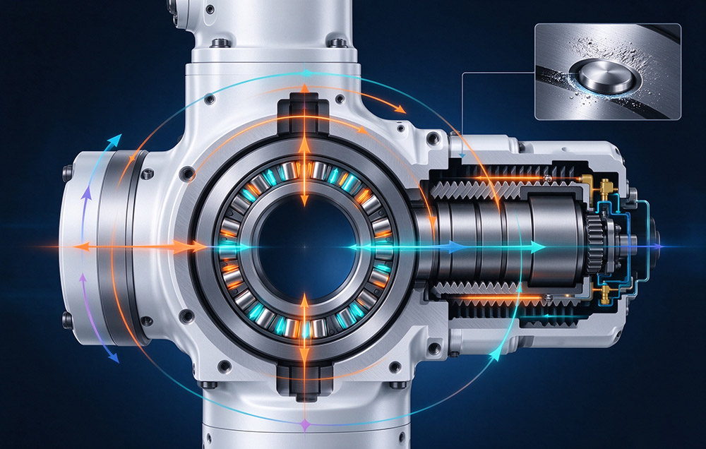
The crossed arrangement gives the bearing its role: as the roller axes alternate, one bearing can resist radial force, axial force, and moment load. This helps support a compact joint envelope containing a reducer, motor, and feedback components without requiring a separate bearing support in many designs. The exact arrangement depends on the joint architecture, as detailed in our guide to robot joint types.
The difficulty sits in the contact. Inner and outer ring raceway dimensions, roller diameter consistency, and assembled clearance are held in microns. Any one drifting out of tolerance shows up as reduced running accuracy or insufficient stiffness, not as a visible defect. Raceway roughness governs fatigue life and noise level, which keeps grinding inside a narrow process window.
Preload is where stiffness and assembly risk trade against each other. A small internal clearance raises stiffness and improves repeatability under reversing load, but it narrows the assembly window and increases sensitivity to thermal deformation. With a large clearance, the joint assembles easily, yet it loses stiffness and deflection under moment load grows. A controlled preload is therefore a process result rather than a tolerance band choice.
Why Small Frames and Large Structures Fail for Different Reasons
Two bearings can share a drawing type and a load case, yet present unrelated manufacturing problems. What separates them is the ratio of the tolerance held to the size of the part that holds it.
Small Frame Bearings
From a few millimeters to a little over ten millimeters of outside diameter, the operator space for raceway grinding, roller sorting, and preload assembly is extremely narrow. Metrology must then carry resolution matching the tolerance it measures. Such frames usually run in light-load, high-precision duties, so running accuracy and starting resistance torque matter more than load capacity. Their volumes are higher as well, which shifts priority from single-piece accuracy to stability: insufficient consistency sends the assembly line into selective fitting.
Large Structure Bearings
Large structures fail in the opposite direction. When the section is scaled up, heat treatment uniformity, residual stress, and grinding thermal distortion move final accuracy by larger absolute amounts, and lifting, clamping, and inspection of large parts need dedicated schemes. A non-standard bearing adds a second class of difficulty, because structure, load distribution, and mounting interface may all be new, so the route is planned again, from structure design to machining. What matters is whether a proven process capability transfers to a shape that has not been produced before.
| Aspect | Small Frames | Large and Non-Standard Structures |
|---|---|---|
| Dimensional control | Raceway size, roller consistency, and clearance held in microns; each error keeps the same relative influence | Heat treatment uniformity, residual stress, and grinding distortion act on larger absolute values |
| Practical limit | Little operator space for grinding, sorting, and preload | Lifting, clamping, and inspection of large parts; route planned for the new form |
| Priority | Batch stability, so that assembly avoids selective fitting | Transfer of proven capability to a new shape |
Both cases sit inside one production scope. Raceway grinding, roller sorting, assembly preload, and inspection are process families the strain wave gear series already depends on. Sizes 3 to 58, with outside diameters from 13 mm to 246 mm, demand the same micron-level discipline on flexspline and circular spline. Producing the cross roller bearings in the same organization lets the two tolerance stacks be balanced at the design stage instead of being matched at assembly.
Moment Load and Bearing Life in Integrated Units
Bearing selection in an integrated unit cannot be separated from the reducer and the module structure. Laifual Drive joint modules cover an outside-diameter range of 40 mm to 190 mm across low-voltage DC and high-voltage AC families. The DC family uses a 48 V supply, while the AC family uses 220 V. Hollow-shaft configuration, motor, drive, feedback, and other interfaces should be confirmed against the selected model. In unit-type designs, the output support and external-load path must be evaluated as one assembly.
Moment Load on the Output Support
Moment load drives the design on an arm axis. At the end of a link, a payload acts at a distance from the bearing center, and that offset turns a modest force into an overturning moment on the output support. The moment figure never stands alone, because the axial and radial components of the same case share raceway contact with it. Permissible moment falls as axial load rises. A bearing that passes on moment load alone can still fail the combined check.
Bearing Life and the Check Set
Bearing life is evaluated over the duty cycle using the operating speed and load spectrum, and the calculated result should meet the design-life requirement for the selected application. Rated torque in the relevant catalog is defined at a rated input speed of 2,000 rpm, so the actual input-speed profile belongs in the calculation as well. Confirm the applicable limits in the technical data for our joint modules.
| Check | Criterion |
|---|---|
| Average load torque | Duty cycle average must stay inside the permissible average load torque of the size |
| Average input speed Ni av | Must stay inside the permissible average input speed |
| Maximum input speed Ni max | Must stay inside the permissible maximum input speed |
| Moment load | Combined radial, axial, and moment case must pass; permissible moment falls as axial load rises |
| Bearing life | Calculated life must exceed the 10,000 to 15,000 hour design life target |
| Static safety factor | Raceway protected from brinelling under the peak load of an emergency stop, a collision, or a power loss |
Static Safety Factor Under Peak Load
Static safety factor covers the events that averaging hides. It compares the static load rating with the peak load possible during an emergency stop, a collision, or a power loss, and that protects the raceway from brinelling, a deformation that no later calibration removes.
Installation, Sealing and Surface Protection
Bearing performance in a joint depends on the surrounding structure and assembly. Sealing arrangements and groove dimensions are model- or series-specific; confirm the released drawing and applicable assembly instructions for the selected strain wave gear. Assembly requirements may include seals at the input fixed end and output end, as well as grease fill in the flexspline cavity.
Protection requirements should follow the application and the selected model’s specification. Where IP67 protection is specified, the complete sealing arrangement and assembly process must meet that rating. Some precision bearings and T-type joints receive black oxide treatment, an oxidation process that can improve corrosion resistance. Surface treatment and sealing should be confirmed without assuming they apply to every product in the range.
Feedback and communication options vary by product family and model. The low-voltage DC family supports CANopen, CAN FD, EtherCAT, and Modbus options; the high-voltage AC family uses BiSS-C and TAMAGAWA interfaces as specified for the relevant products. Confirm encoder type, protocol, driver arrangement, and control strategy against the selected model. Absolute feedback alone does not establish that every system supports multi-turn retention after power loss or dual-loop position control. Review the latest requirements in our robotics applications guide.
Technical Data
Table 3 summarizes representative product-range information and selection items. Verify model-dependent values against the current catalog and released technical documentation.
| Parameter | Specification | Note |
|---|---|---|
| Positioning accuracy and service life | Confirm for the selected model and duty cycle | Joint-level results depend on the complete assembly and operating conditions |
| Backlash, by series | Catalog value varies by series | Confirm the specified series and measurement conditions |
| Ratios and sizes | 30:1 to 160:1; size 3 to size 58; 13 mm to 246 mm outside diameter | Verify available combinations in the current catalog |
| Joint modules | 40 mm to 190 mm outside-diameter range; 48 V DC and 220 V AC families | Protection, payload, and configuration depend on the selected model |
| Rated torque | Permissible continuous load torque at 2,000 rpm input | Confirm the relevant catalog definition and operating point |
| Delta profile | Performance depends on the specific reducer design and test conditions | Avoid generalizing numerical improvements without product-specific validation |
| Interfaces and company data | DC low-voltage family: CANopen, CAN FD, EtherCAT, and Modbus; AC high-voltage family: BiSS-C and TAMAGAWA | 52,000 square meters; R&D team over 100; flexspline self-supply above 80% in 2025; cumulative deliveries above 1,000,000 harmonic reducers; listed as 03952.HK |
Bearing Selection and Load Path Design
Selection starts from the joint, not from the bearing. The sequence below applies whether the bearing is ordered as a component or supplied inside a module. It also covers the planetary gearboxes and precision bearings combination on axes where a first stage precedes the strain wave gear.
1
Define the load path before the load number. Establish which stiffness and clearance belongs to the gear mesh and which belongs to the bearing support, because in an integrated unit one element carries both.
2
Reduce the duty cycle to average load torque, average input speed Ni av, and maximum input speed Ni max, and compare each against the permissible value for the candidate size.
3
Resolve the external load at the output flange into radial force, axial force, and overturning moment. Moment load usually binds on an arm axis and must be evaluated with the axial component.
4
Check bearing life against the design life target of 10,000 to 15,000 hours. A larger frame is normally more effective than a change of preload where calculated life falls short, since raceway contact area grows with the frame.
5
Set the static safety factor from the peak load the axis can produce, not from nominal duty, so that an emergency stop or a collision cannot brinell the raceway.
6
Fix preload, fit, and sealing as one assembly specification: preload sets stiffness and repeatability, the fit sets the assembly window and the thermal behavior, and the seal interfaces sit on the same joint face.
7
Match the control interface to the mechanical requirements. Confirm the encoder type, communication protocol, driver arrangement, and controller support for the selected model. Where dual-loop control or multi-turn retention is required, verify that the complete encoder, drive, and controller configuration explicitly supports it.
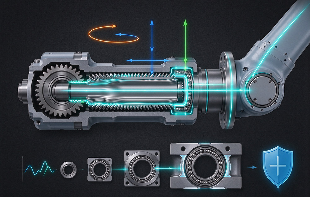
Load-path design is the part that does not appear on a bearing drawing. A joint is limited by the compliance and variation of its complete mechanical chain, so a bearing chosen for its moment rating alone may still leave the axis short of target. Work from the load case towards the drawing, and verify average torque, both speed limits, moment load, bearing life, and static safety factor as one set.