
Transmission in Continuous Duty Battery and Solar Production Lines
Learn how to size strain wave gears for continuous battery and solar lines. Master thermal equilibrium, grease service intervals, and 24/7 takt-time checks.
 September 08, 2026
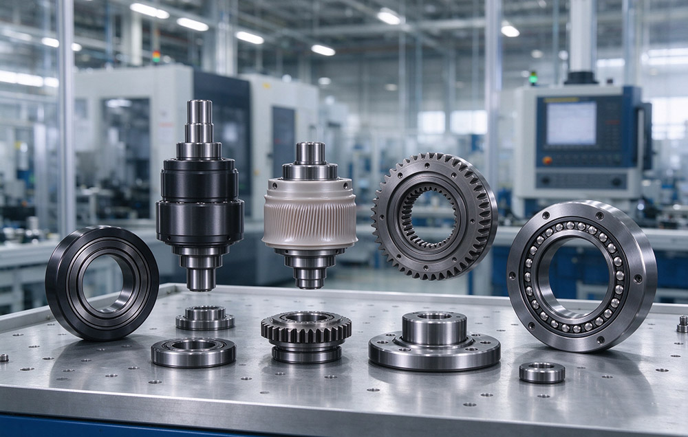
 > Transmission in Continuous Duty Battery and Solar Production Lines
A harmonic reducer on a battery or solar line is a strain wave gear set whose behavior the continuous duty cycle fixes as much as its torque. Equipment starts with a campaign and runs on, stops counted per year, not per shift. The gear set never returns to ambient temperature, and the lubricant never gets a rest interval.
Battery cell stacking and winding, tab welding, solar string welding, and module assembly all follow that pattern. Takt times are counted in seconds, a stalled axis stops every station downstream, and position consistency has to hold from the first unit of a shift to the last.
Thermal equilibrium in a gear set that never cools comes first, then the grease interval that sets the maintenance window behind the design life of 10,000 to 15,000 hours. Takt time moves the operating point away from the rated 2,000 rpm input, and the closing checks belong in the specification before a size is fixed. The same logic applies to a component reducer and to the joint modules that integrate the gear set with a motor, an encoder, and a drive in one housing.
Thermal Equilibrium in a Line That Does Not Stop
Where the Equilibrium Temperature Settles
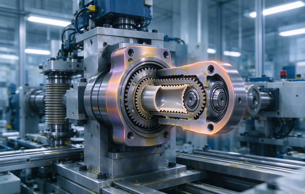
Intermittent duty gives a gear set time to shed heat; continuous duty gives it none. After the first hours of a campaign, temperature settles where heat from the mesh, bearings, and seals equals heat leaving through the housing, mounting face, and surrounding air. Equilibrium depends on enclosure ambient temperature, convection surface, thermal resistance between the reducer flange and the machine frame, and load torque as a fraction of rated value.
Running Above the Grease Temperature Rating
Above the lubricant’s temperature rating, base oil migrates out of the grease thickener faster, the film at the tooth flank thins, and running torque rises slightly, adding heat to the same path. The process measures position at the tool, so the first symptom is a slow loss of position consistency, with no thermal alarm.
The delta tooth profile in Laifual Drive reducers attacks the source of that heat. Against the conventional double circular arc profile, it raises load capacity by 15% to 30% and lowers temperature rise by 8 to 10 °C. It also reduces the flank area affected by fatigue pitting by more than 30%. Across thousands of running hours a year, that difference decides whether a grease charge lasts a planned interval.
Duty Patterns and Their Design Responses
| Duty Pattern | Thermal Behavior | Dominant Transmission Effect | Design Response |
|---|---|---|---|
| Intermittent axis, machine tool use | Returns toward ambient between cycles | Peak torque and torsional stiffness | Size on peak load, verify average torque |
| Continuous stacking or winding | Equilibrium reached and then held | Grease life and slow thermal drift | Size on average torque with margin, fix a grease interval |
| Continuous string welding and transfer | Equilibrium plus a high cycle count | Repeatability over millions of cycles | Fix the backlash class, check the output bearing |
| Continuous with rapid traverse | Equilibrium plus frequent acceleration | Inertia torque, cyclic load on the bearing | Check Ni av and Ni max, verify moment load |
Lubrication, Maintenance Windows and the Cost of a Stop
On a line that never pauses, lubrication sets the maintenance calendar. Grease life shortens as the equilibrium temperature rises, so two identical reducers on one machine can reach their interval months apart against a hot frame. Define the interval from the measured working temperature under real duty. A rising running temperature at constant load points to the seal or the grease.
Seal and groove geometry is specified by family (FHT-I, FHT-II, and FHT-V). Assembly requires sealing at the input fixed end and the output side, with a defined grease fill of the flexspline cavity. On an integrated unit, that boundary is closed once, because the servo motor, the strain wave gear set, the encoder, and the drive share one IP67 housing. Dust or liquid has fewer paths to a bearing or a cable entry.
A stop on one axis halts every station downstream and costs the units in process. Where a campaign runs for days, the gap between a planned and an unplanned stop is measured in output. A size with thermal margin and a sealed housing is often cheaper overall, even when the payload calculation alone would allow something smaller. A long interval keeps the maintenance window predictable, which depends on how the tooth flank and the bearing seat are held in production, the subject of precision manufacturing at Laifual Drive.
Life Definitions and the Rated Point at 2,000 rpm
The rated torque of a Laifual Drive reducer is the permissible continuous load torque at a rated input speed of 2,000 rpm, so the catalog value already assumes continuous duty. A cycle spent mostly below 2,000 rpm cannot be read off the rated torque column, because the permissible average load torque governs, not the nominal speed.
Takt time fixes the speed. Rotation per cycle follows from the process and the cycle period from the takt, so input speed is output speed times the ratio, from 30:1 to 160:1. An axis with a short takt and a large indexing angle can exceed the rated speed for part of every cycle, which makes Ni max a binding constraint. A long dwell with a heavy tool sits low in speed and high in torque, where the average load torque check governs.
Acceleration changes the picture. Frequent start and stop turns the inertia of the moving parts into cyclic load on the output bearing and a torque peak on top of the process load. The lightweight FSN series cuts mass by about 30% at the same rated torque, stiffness, and transmission accuracy, lowering the inertia the motor accelerates on every reversal.
Repeatability under those reversals comes from the gear set, whose multi-tooth mesh holds backlash to the class of the series.
| Parameter | Definition | Reference Condition |
|---|---|---|
| Rated torque | Permissible continuous load torque of the size | Rated input speed 2,000 rpm |
| Permissible average load torque | Upper limit for the cycle average Tav | Catalog value per size and ratio |
| Average input speed Ni av | Cycle average of input speed | Compared with the limit for the size |
| Maximum input speed Ni max | Highest input speed occurring in the cycle | Compared with the limit for the size |
| Backlash | Lost motion referred to the output | 60, 30, or 20 arcseconds or less, by series |
| Positioning accuracy | Output accuracy of the assembly | ±15 arcseconds |
| Design life | Rated service life under specified conditions | 10,000 to 15,000 hours |
| Continuous running life | Endurance running of the delta tooth profile | Above 15,000 hours |
| Output bearing checks | Maximum moment load, bearing life, static safety factor | Unit type with integrated cross-roller bearing |
Technical Data
One tooth engagement logic and one accuracy class can be specified at both ends of a machine, keeping the control model and spare parts uniform.
| Item | Coverage |
|---|---|
| Harmonic reducer sizes | Size 3 to size 58, ratios 30:1 to 160:1, outside diameter 13 mm to 246 mm |
| Reducer series | FSS, FSF, FSN, FSG, FHT, FHG, FHD, FHN, FBS-U, FBS-C, and Mini |
| Backlash classes | 60, 30, or 20 arcseconds or less, by series |
| Positioning accuracy | ±15 arcseconds |
| Design life | 10,000 to 15,000 hours under specified conditions |
| Lightweight series | FSN, about 30% lower mass at the same rated torque, stiffness, and transmission accuracy |
| Joint module outside diameter | 40 mm to 190 mm, continuous across the range |
| DC low-voltage platform | 48 V DC with integrated servo drive; models L40I, L52I, L60I, L70I, L80I, L90I, L110I, L142I, L170I, and L190I |
| AC high-voltage platform | 220 V AC; models M70, M80, M90, M110, M142, M170, and M190 |
| Robot arm payload classes | 3 kg to 20 kg |
| Protection and protocols | DC 48 V: CANopen, CAN FD, EtherCAT, and Modbus; AC 220 V: BiSS-C and TAMAGAWA |
| Motor insulation | Class F, 155 °C |
The 48 V platform with an integrated drive suits distributed axes with a small cabinet. The 220 V frames with a hollow shaft route cables through the joint on high-power arms, the case the AC high voltage joint modules cover. Where an axis needs a bare reducer, the strain wave gear series covers the same ratios and accuracy classes for the machine builder’s own housing.
Verifying an Axis on a Continuous Duty Line
1
Record the real duty cycle: rotation per cycle, cycle period, dwell, load torque profile, and enclosure ambient temperature.
2
Derive the average load torque Tav over the cycle, then select a size whose permissible average load torque at 2,000 rpm input covers it with margin for enclosure temperature.
3
Check Ni av and Ni max against the size limits, using the takt time to establish how much of the cycle runs near or above the rated speed.
4
For a unit-type reducer or joint module with an integrated cross-roller bearing, verify maximum moment load, bearing life, and static safety factor.
5
Select the backlash class against the accuracy the process needs, and confirm that accuracy holds across the maintenance interval.
6
Fix the sealing variant and the grease against the ambient condition and the equilibrium temperature, then recheck the thermal margin with aged grease.
7
Confirm the encoder and control interface. An absolute encoder that retains position and multi-turn count through a power interruption removes a homing cycle from every restart, and the low-voltage platform offers -C (CANopen) and -E (EtherCAT) versions.
8
Set the service interval from the expected working temperature, and confirm lead time against the line commissioning date for a non-standard interface or ratio.
Application Notes for Battery and Solar Lines
Contamination Control Where Metal Fines Are a Product Risk
A battery workshop treats wear debris from any moving part as a product risk and a contamination source. A sealed housing with a limited number of openings shortens the exposed path. Black oxide on T-type joints and selected precision bearings forms a dense oxide film on ferrous surfaces. That film resists rust where a bare machined face would corrode in a humid workshop.
Installation Practice and Condition Checks
Mount the axis so fluid cannot collect against a seal lip, and route the cable with a drip loop below the connector.
Keep housing openings to a minimum in a dust-sensitive area, and seal any fastener that passes through the wall.
Judge the axis by running temperature and position consistency together, since a rise in either at constant duty points to the seal or grease.
Position consistency over millions of reversals also depends on how the mesh behaves, as treated in precision actuators in modern applications. A plant that controls its own flexspline forging, gear shaping, and heat treatment shortens the route from a process change to the flank it affects, as set out in automated manufacturing and precision. Laifual Drive runs that chain in-house on a 52,000 m² site with more than 100 engineers in research and development and more than one million harmonic reducers shipped. A non-standard proposal is normally available in about two weeks, with a sample in about four.
Specifying for Continuous Duty
Thermal equilibrium, grease life, and the maintenance interval come first. The rated figures assume continuous operation at a defined speed, so the axis must hold accuracy across the whole interval. Takt time then sets the speed check, since a short cycle can breach the maximum input speed limit while the average stays comfortable.
A specification that survives a campaign records the duty cycle, sizes on the permissible average load torque with margin for the enclosure, and verifies the output bearing under acceleration. Those records hold the rated torque at 2,000 rpm input and the design life of 10,000 to 15,000 hours valid for an automation line expected to run without a break. Backlash stays at 60, 30, or 20 arcseconds or less, and positioning accuracy at ±15 arcseconds.
Plan Your Continuous-Duty Production Line
Connect with our automation application engineering desk for thermal dissipation calculations, grease life modeling, and 24/7 continuous duty sizing support.