
Flexspline Life Under Repeated Deformation
Learn what governs flexspline fatigue life in strain wave gears. Explore alternating bending stress, delta tooth profiles, and 10,000–15,000 hour ratings.
 October 23, 2026
 > Flexspline Life Under Repeated Deformation
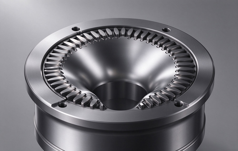
A strain wave gear transmits motion by deforming its flexspline. Its wave generator bends a thin-walled cup or hat section into an elliptical shape, and the displaced teeth engage the circular spline at the two major axes. The tooth-count difference between the two gears produces the reduction. This cup is the one component required to change shape on every input revolution instead of holding it. Flexspline fatigue life is the design quantity that answers whether it can do so for the working life of a machine without cracking, losing tooth form, or drifting out of positioning accuracy.
The question behind that quantity looks contradictory. A wall bent thousands of times per minute should be governed by fatigue, yet production flexsplines run for years without fracture. The resolution lies in the stress the wall carries in normal operation, which is held below the level at which a crack initiates and propagates in the steel. That margin between the two is created at the design stage and preserved by the state of the material beneath the surface.
This article covers what loads the flexspline, how tooth form and material state act on its life, and how the 10,000 to 15,000 hour design life is rated.
Why a Flexspline Survives Millions of Deformations
The flexspline does not see one stress but several, at different places, ending its life in different ways. At the tooth root and around the fillet where the cup meets the flange, the ovalization of the wall produces an alternating bending stress that reverses twice per input revolution. On the engaged flanks, the same mesh that transmits torque applies a contact stress with rolling and sliding, and it is this component that produces pitting and wear over time. Assembly conditions add a largely static stress: flange clamping, bearing seats, and bolt preload leave the wall loaded at a mean level before any torque is applied.
The engineering principle that keeps the first of these from causing fracture is the fatigue limit of steel. For a steel under cyclic stress, there is an amplitude below which an initiated crack stops growing, so flexspline operation has a bounded working range. Production flexsplines are designed so that the alternating bending stress at the root and the fillet stays inside that range. Life is then governed by the clearance to that limit rather than by the raw count of deformation cycles. Wall thickness, ovality, the transition to the flange, and the stiffness of the support behind it set that stress.
Material state decides how much the geometry can be asked to carry. A uniform and clean microstructure with a controlled grain size delays crack initiation. A hardness gradient that is hard at the surface and tough in the core resists flank wear while still absorbing deformation energy through the wall. Compressive residual stress in the surface layers opposes the tensile side of the bending cycle and raises the effective fatigue limit. All three are outcomes of melting, forging, and heat treatment.
Mean stress matters as much as the alternating part. Preload applied through an over-constrained mounting shifts the mean point of the cycle and lowers the allowable amplitude, which is why mounting accuracy appears in Table 1 alongside the load itself.
| Load Component | Where It Acts | Design Variable That Sets Its Magnitude | Failure Mode When the Margin Is Lost |
|---|---|---|---|
| Alternating bending stress | Tooth root and cup fillet, reversing each input revolution | Wall thickness, ovality, transition geometry | Fatigue crack initiating at the fillet |
| Tooth flank contact stress | Engaged flanks under rolling and sliding | Tooth form, surface hardness, profile accuracy | Pitting and flank wear, then loss of positioning accuracy |
| Mean stress from assembly | Flange, bearing seats, clamped interfaces | Interface fit, bolt preload, mounting accuracy | Lower allowable amplitude |
What Tooth Form Optimization Changes
The tooth form is the second lever on flexspline life, and it acts on the flank side of the balance. Because the flexspline flank passes through the mesh in a deflected state, contact is never uniform along the tooth. Load concentrates where curvature and deflected geometry bring the surfaces together, and the pressure distribution moves as the wave generator turns. A profile that keeps the contact patch broad and the sliding low holds contact stress down, and contact stress is what converts into pitting and flank wear.
In the Laifual Drive range, the delta profile is a multi-segment continuously variable curvature arc developed on the basis of the conventional double circular arc form. Its purpose is that contact behavior: an arc set that follows the deflected tooth geometry closely enough to spread load over a wider bearing area. Table 2 lists them as one set, because load capacity, temperature rise, pitting area, and running life are consequences of the same change in geometry.
| Characteristic | Conventional Double Circular Arc Profile | Delta Profile |
|---|---|---|
| Load capacity | Reference | 15 to 30 percent higher |
| Temperature rise in operation | Reference | 8 to 10 °C lower |
| Contact area exposed to pitting | Reference | More than 30 percent smaller |
| Continuous running life | Reference | Above 15,000 hours |
Temperature rise belongs on that list because it is itself a wear mechanism. Heat is generated where sliding occurs in the mesh, and the same sliding thins the lubricant film and lowers the load the flank can carry. Lowering the rise slows the wear that consumes tooth form accuracy, and the running life above 15,000 hours is the accumulated result.
Flank wear also feeds back into the positioning characteristics of the reducer. As material leaves the engaged flanks, the fit between flexspline and circular spline loosens. That fit has to be held for the backlash and lost motion that low backlash in strain wave gears deliver at the start of life. Life is therefore a matter of survival, and of the length of time for which the promised accuracy is available to the machine.
Where Flexspline Life Is Lost in Service
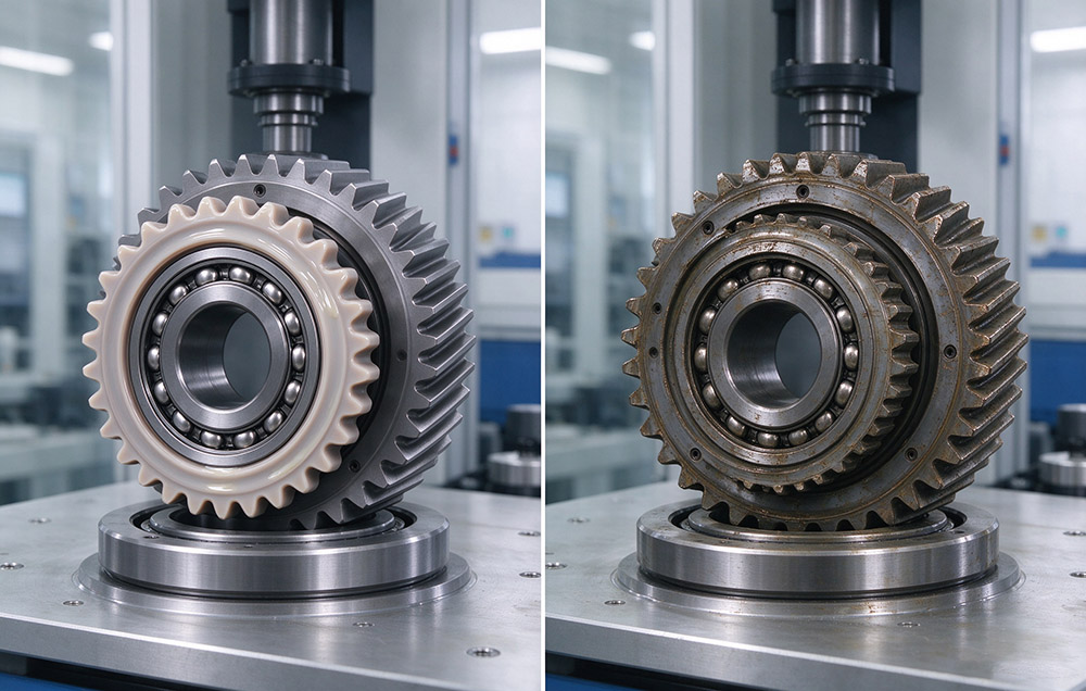
Three failure modes account for the end of a flexspline’s useful life, and they are distinguished by where they appear and what they measure. Fatigue fracture of the wall or the fillet produces a sudden loss of the load path and is a strength and microstructure problem. Tooth flank wear and pitting develop gradually and are measured as a loss of accuracy and a rise in backlash long before they become a mechanical failure. Bearing wear in unit types with an integrated cross roller bearing appears as a loss of stiffness and a rise in the moment load reaction. A life result that does not say which mode ended the test cannot be used as a design input.
Why the Failure Modes Are Tested Separately
That separation is why fatigue testing stands as a dedicated capability, separate from routine acceptance checks. Fatigue fracture, tooth flank wear, and cross roller bearing wear each map to a different link in the chain. The forged wall and its structure map to fracture, the tooth form and the surface left by cutting map to flank wear, and internal bearing production and preload map to bearing wear. A program that runs all three modes against the same process record can distinguish a parameter shift from an understated duty cycle.
Vibration and acoustic behavior act as the field-side indicator of the same mechanisms. A rising vibration level at the joint output, or a change in the noise signature under reversing load, typically precedes the loss of accuracy that flank wear would otherwise announce later. Tracking vibration control in harmonic reducers against the baseline of a new unit gives the maintenance side an early signal instead of a post-failure diagnosis. Life scatter inside a shipment is the other reason for tracking the modes separately.
Fatigue Testing and Maintenance Practice
Testing establishes the life figure, and maintenance allows it to be reached on a machine. Three variables can be observed: lubrication, monitoring, and replacement policy.
Lubrication and the Regreasing Interval
Grease fills the flexspline cavity at build, and the tooth mesh, the flexspline outer surface, and the integrated bearing all draw on that charge. Once it has lost its base oil, thickened, or taken in wear debris, grease stops delivering the film the low contact stress design depends on, and the wear rate rises accordingly. Production equipment with a high duty cycle or a hot ambient reaches that condition sooner, so the regreasing interval follows the duty cycle instead of a calendar value.
Monitoring Without Dismantling
Backlash and lost motion measured at the output, starting torque, temperature rise over the housing, and vibration on the input side together describe the wear state without opening the drive. The trend matters more than any single reading. A slow increase in backlash alongside a stable temperature points to flank wear, while a temperature rise with no change in accuracy points towards lubrication or preload. Working to a documented harmonic reducer maintenance schedule keeps those readings comparable between units and visits.
Replacement Policy
Because the dominant modes progress slowly, a flexspline operated inside its rated window is normally retired on an accuracy or vibration criterion rather than on fracture. When a unit reaches the end of its life earlier than the rated figure suggests, the useful comparison is its measured load spectrum and mounting against the assumptions behind the rating. Both shift the fatigue calculation.
Design Life and Rating Practice
Design life in the Laifual Drive catalog is 10,000–15,000 hours, and it is defined against a stated condition rather than issued as a bare number. The reference condition is rated torque, the permissible continuous load torque at a rated input speed of 2,000 rpm. At that speed, a two-lobe wave generator deforms any given wall section twice per input revolution, so the deformation rate is 4,000 cycles per minute. A 10,000-hour life corresponds to roughly 2.4 billion deformation cycles, and the design margin protects a duty measured in billions of cycles.
| Parameter | Definition | Consequence for the Design |
|---|---|---|
| Rated torque | Permissible continuous load torque at a rated input speed of 2,000 rpm | Reference for the duty cycle comparison |
| Design life | 10,000–15,000 hours | Quoted at the rated condition |
| Average load torque | Mean of the load spectrum | Stays within the permissible average limit |
| Average and maximum input speed | Mean and peak of the speed spectrum | Both are check limits and both change the cycle count |
| Positioning accuracy | ±15 arcseconds | The accuracy that has to survive to end of life |
| Backlash by series | ≤60, ≤30, and ≤20 arcseconds | Population values |
Rating a joint from this table means starting with the load spectrum rather than the peak. A joint that spends most of its cycle at part load cannot be rated on its maximum torque alone. Running above the rated input speed, the same joint accumulates deformation cycles faster than the hour count suggests. Four checks follow: the average load torque against the permissible average limit, and the average and maximum input speeds against their limits. For unit types with an integrated cross roller bearing, the maximum moment load, bearing life, and static safety factor are checked together with them.
Where a duty cycle falls outside the standard rating window, the quoted life figure no longer applies as written. Within that window, the range is wide, with the strain wave gear series covering size 3 to size 58, reduction ratios of 30:1–160:1, and outside diameters of 13–246 mm.
When the envelope, the mounting interface, or the accuracy requirement falls outside it, our custom design service specifies the part around the duty instead of asking the standard part to absorb it. Robotics joints are the clearest case of a duty dominated by cycle count more than by torque, which is why robotics applications rate the joint on its motion profile as much as on its payload. For full joint assemblies, explore our joint modules.
Flexspline life is therefore the output of a comparison between the duty cycle and a design that holds the alternating stress inside the material limit for the whole of it. Both the duty cycle and the design decide it.
Optimize Your Strain Wave Actuator Lifecycle
Contact our R&D engineering laboratory for accelerated S-N fatigue curve data, duty spectrum verification, and application-specific flexspline design services.