
Gear Cutting Cycle Time in Precision Reducer Production
Explore how reducing gear cutting cycle time from 2–3 hours to under 15 minutes drives batch consistency, faster prototyping, and custom strain wave gears.
 October 21, 2026
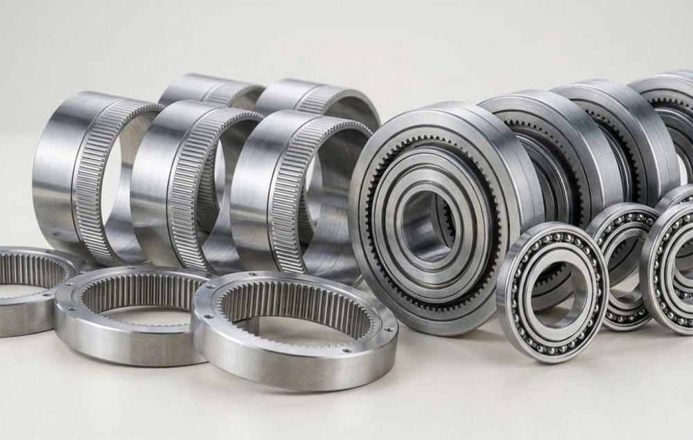
 > Gear Cutting Cycle Time in Precision Reducer Production
Gear cutting is the generating operation that forms the tooth flanks of the flexspline and the circular spline, and in a strain wave gear, it fixes the accuracy every later stage has to work around. In precision reducer production, it is also the longest single step in the machining chain. That length turns its cycle time into a first-order constraint on capacity, part-to-part consistency, and how quickly a non-standard unit can be quoted and delivered. A gear cutting precision reducer program is therefore organized around one practical question: how much of the tooth geometry can be produced in one continuous cut without giving up flank quality.
Laifual Drive developed its own gear-cutting process, and the figures it produces are the subject of this article. Core component machining time has moved from 2–3 hours to less than 15 minutes. That result reaches further than throughput: it changes what the quality system has to verify and moves the boundary between what a customer orders from a catalog and what can be built to a drawing. Published reference data is used throughout, with rated torque defined at 2,000 rpm input, positioning accuracy stated as ±15 arcsec, and design life of 10,000–15,000 hours.
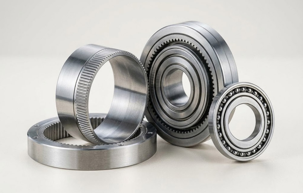
Where Gear Cutting Sits in the Production Chain
Tooth generation is neither the first nor the last operation, and its cycle time matters because of what surrounds it. The chain begins with material and ends with a tested unit, and each stage hands a tolerance to the next. Upstream, blank condition decides how the tool enters the material; downstream, lapping and assembly can only work with the geometry they receive.
That position makes gear cutting a bottleneck by construction. Flank geometry, tooth spacing, and lead are created here, so backlash, lost motion, and torsional stiffness are all quantified downstream, and no later operation recovers spacing generated badly. A slow cutting step also delays every operation behind it, which is why machines, tooling, and labor concentrate at this point in the shop.
A neighboring process solves the same problem with different tool geometry. Precision gear shaping also generates the flank, but with a reciprocating cutter rather than a continuous rolling path, and is covered separately in our notes on precision gear shaping technology. Both belong to the same family of generating methods, and a plant that runs both can match the method to the module, batch size, and flank form a given profile requires.
| Stage | Output of the Stage | What It Governs Downstream |
|---|---|---|
| Special steel smelting and flexspline forging | Near-net-shape blank with controlled material condition | Fatigue strength available to the flexspline |
| Blank preparation and turning | Reference diameters and mounting faces | Runout of the assembled unit |
| Gear cutting | Tooth profile, spacing, and lead | Backlash, lost motion, and torsional stiffness |
| Heat treatment | Core hardness and internal stress state | Rated torque and design life |
| Assembly and test | Complete unit with measured output | Backlash class, hysteresis, and repeatability |
The Generating Cut and How the Cycle Time Comes Down
Gear cutting works on the generating principle: tool and workpiece rotate in a coordinated relationship, and the flank emerges as the envelope of successive tool positions rather than as a form copied from a cutter. Classically, the limitation lies outside the cutting action, in everything arranged around it. A component may pass through several operations and re-clampings before the tooth is complete, and each interruption adds setup time, fixture time, and another opportunity for reference error.
The shop process at Laifual Drive redesigns tool motion and cutting path so that a higher material removal rate is reached while flank quality is held. What was a multi-operation sequence becomes one continuous cut: 2–3 hours down to less than 15 minutes on core components, approximately eight times faster on the same class of part.
| Attribute | Conventional Multi-Operation Generation | Single Continuous Gear Cutting |
|---|---|---|
| Setups per component | Several re-clampings between operations | One continuous cut |
| Machining time per core component | 2–3 hours | Less than 15 minutes |
| Relative output per machine hour | Baseline | About eight times |
| Error sources | Setup and re-clamping errors stack up | Fewer referenced setups to control |
| Flank quality | Dependent on handling between operations | Carried through the same pass |
Saving in non-cutting time deserves as much attention as the saving in cutting time. Fewer clampings means fewer fixture changes, less manual intervention, and less handling between operations. Handling is where damage risk and reference drift accumulate on a precision part, so removing handling steps supports accuracy at the same time as speed. A shorter cycle therefore carries no penalty in tolerance.
Capacity and Consistency Effects
Output Ceiling at Constant Machine Count
Efficiency and capacity are two different quantities, but they are tightly linked. With the machine count held constant, unit time down by a factor of about eight raises the ceiling on output by a similar factor, provided blank supply upstream and finishing capacity downstream keep pace. Vertical integration keeps that condition true here. Special steel smelting and precision flexspline forging are in-house, with flexspline self-supply above 80% in 2025. Gear cutting, heat treatment, cross roller bearings, and final assembly are all carried out internally, supported by automated production lines in the Shengzhou plant.
Why One Pass Narrows Batch Spread
Consistency improves for a mechanical reason. When the tooth profile is generated in one pass, it is referenced to the same surfaces throughout, and thermal conditions stay inside a single envelope. Tooth spacing and contact pattern therefore vary less across a batch. Backlash classes of ≤60, ≤30, and ≤20 arcsec by series, positioning accuracy of ±15 arcsec, and design life of 10,000–15,000 hours are unit-level figures. They are reachable only when tooth generation repeats part to part. Speed that comes from consolidating setups reinforces the quality outcome instead of competing with it.
From Geometry Consistency to Life Figures
The same argument applies to life. Flank load capacity follows from geometry and material state, so a process that holds geometry across a batch lets life figures be attributed to the design. Dedicated fatigue testing then checks that attribution over long running instead of a short acceptance sample.
Cycle Time Reduction and the Quality System
A shorter cycle counts as an improvement only while the process stays capable. The quality system around gear cutting therefore answers three questions. It asks whether the machine holds the geometry across a batch, whether the material state supports the flank loads, and whether the assembled unit meets its rated figures.
Geometry
Tooth profile, spacing, and lead are verified against the design profile across a batch, not on a first article alone.
Material State
In-house heat treatment, covering quenching, tempering, austempering, and vacuum treatment, sets core hardness and controls the internal stress that would otherwise move the flank in service.
Assembly Outcome
Backlash class, hysteresis, repeatability, and torsional stiffness are measured on the finished unit, where every upstream deviation finally shows up.
Tooth profile and cutting process were developed as one system, and that is what makes those three levels checkable. The gear tooth profile in the delta design uses multi-segment variable-curvature arcs, and the machine path that produces it was designed against that geometry in the same program. Process defines what the profile can be cut to, and profile defines what tool and path must do. A cutting process bought from outside arrives with the two definitions separate, to be reconciled by trial.
Scale is a useful check on that relationship. Laifual Drive has delivered more than one million harmonic reducers cumulatively and is listed in Hong Kong under 03952.HK. It also runs joint research platforms with Chongqing University, Zhejiang University of Technology, and Huazhong University of Science and Technology. Volume of that order only holds up if a fast process is also a stable one, because a fifteen-minute cycle leaves no room for corrective manual work built into the plan.
Effect on Lead Time and Customization
For catalog products, lead time is a planning question. For non-standard products, it is close to the product itself. Non-standard work carries a structural difficulty: development effort is high, batch size is small, and unit cost absorbs all of it. Under a conventional process, both cutting time and tooling preparation were long, so such an order was technically possible but commercially hard to place. A customer needing a modified interface often lived with a standard size instead.
At a cycle time in the fifteen-minute range, the economics of one unit or a small batch change. Published response times reflect that: non-standard feasibility and scheme work at about two weeks, sample delivery at about four weeks. For a robot development program, where early stages involve repeated trial builds and validation, sample turnaround largely sets the development rhythm. Moving delivery from more than a month to within four weeks makes room for roughly twice as many iterations in the same window.
| Program Stage | Published Timeline | Consequence for the Program |
|---|---|---|
| Non-standard feasibility and scheme | About 2 weeks | Interface and rating settled before tooling commitment |
| Sample unit delivery | About 4 weeks | Validation loops fit inside a development quarter |
Custom interfaces are where those timelines are spent. Modified housings, shaft ends, and mounting patterns are handled through our custom design service. Variants such as hollow-shaft FHT carry their own sealing and assembly requirements, with oil seal and groove dimensions documented per FHT-I, FHT-II, and FHT-V configuration. Documented sealing matters more when a unit is built to a drawing, because the interface is where a fast sample becomes a repeatable product.
Process Capability and Design Freedom
Design freedom in gear work is bounded by the capability of the process that produces the geometry. A profile that cannot be cut to the required spacing, or cannot be cut without burning the flank, is unavailable as a design option no matter how it performs on paper. Profile design and gear cutting development therefore belong to the same group of engineers, so the design can be tailored to the capability that exists. That process is then optimized against a specific intent instead of a generic one.
The delta profile is the clearest example in the current range. It replaces the conventional double circular arc with several arc segments of continuously varying curvature. Its published performance relative to that form is a load capacity improvement of 15% to 30% and a temperature rise reduction of 8 to 10 °C. It also cuts contact area affected by tooth surface fatigue pitting by more than 30%, and extends continuous running-in life beyond 15,000 hours. None of those figures survive on design alone; each requires the cutting process to deliver the intended geometry repeatedly, with the heat-treat condition set to match.
The same principle scales across the catalog. The strain wave gear series covers size 3 to 58 with ratios from 30:1–160:1 and outside diameters from 13–246 mm, hundreds of SKUs generated on one tooth-cutting system. Among them is the lightweight FSN series, which reduces mass by about 30% while holding rated torque, stiffness, and transmission accuracy.
Custom work starts from the same platform. Average load torque is checked against the permissible average load torque, and average and maximum input speed are verified against the duty cycle. Unit types with an integrated cross-roller bearing are additionally checked for maximum moment load, bearing life, and static safety factor. What a customer can ask for is limited by those checks, and what the shop can produce quickly is what makes asking worthwhile.
Gear cutting cycle time is a number on a shop-floor sheet, but in precision reducer production, it propagates outward. It reaches into pricing structure, batch consistency, delivery rhythm, and the range of profiles a designer is willing to propose. A profile is only as free as the machine and tooling behind it, and keeping process development and tooth profile design inside one engineering system is what turns that freedom into published, repeatable performance. For complete integrated solutions, explore our joint modules.
Accelerate Your Custom Reducer Prototyping
Submit your interface drawings and duty profiles to our production engineering team. Benefit from rapid 2-week feasibility analysis and 4-week sample delivery.