Parts, Components and Systems in Precision Transmission Supply
Compare precision transmission supply levels: parts, components, and systems. Learn to select reducers, joint modules, and robotic actuators for your team.
 October 01, 2026
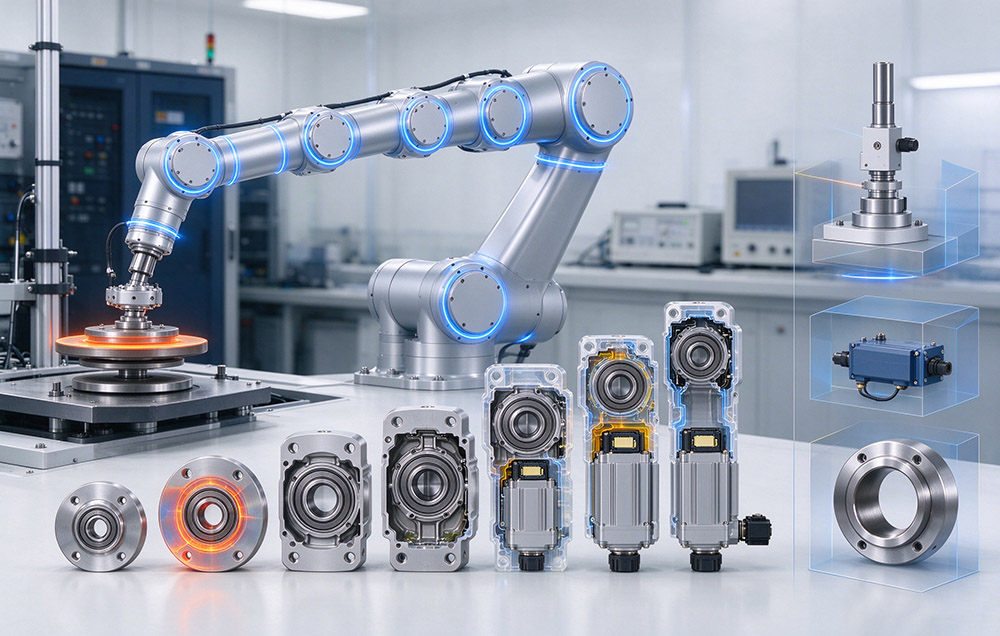

A precision transmission supplier can close the motion chain at three points, and the point of closure defines the level of supply. Delivery at the parts level is a mechanically finished component, leaving motor selection, feedback, sealing, lubrication, and the control loop to the buyer. At the components level the reduction stage arrives integrated with motor, encoder, drive, brake, and torque sensing, so the axis becomes commandable. At the systems level the mechanical interface, kinematic layout, and control architecture close around a task, and the result is validated as a machine.
Each of the three levels describes a delivery scope, and none outranks another on quality; the highest suits the fewest programs. Each level transfers a block of engineering work from buyer to supplier, with interface definition and verification, so the right choice matches a team’s engineering capacity.
Reducers, robotics components, and assembled joints are treated here as levels of supply, each with its own place in the chain. Explore our full product catalog or contact our engineering team for tailored assistance.
Delivery Scope and Interface Responsibility
Every purchase contains the same work items: ratio choice, motor and encoder matching, bearing arrangement, sealing and lubrication, control-loop tuning, and proof of the result.
Work Retained at the Parts Level
At the parts level the work stays with the buyer, who receives a component with a mechanical interface and a data sheet while every electrical and control decision stays open. That suits a buyer that already holds transmission design capability, keeping the bill of materials and performance model in-house.
Coupled Links Handed to the Supplier
Here the supplier takes the tightly coupled links, along with the shaft alignment and commutation setup they bring. A reduction stage, an encoder, and a drive loop cannot be commissioned independently: shaft alignment, encoder mounting tolerance, and commutation setup decide whether rated accuracy appears at the output. Closing them in one unit is why robot actuator basics treat the actuator as one subsystem.
Systems Scope and Switching Cost
At the systems level the load path, structural interface, feedback arrangement, and control architecture are defined together, since a choice in one constrains the others. Engineering hours fall as the level rises while switching cost rises with it: a part can be replaced in one redesign, whereas a system carries a machine’s kinematic model and application knowledge.
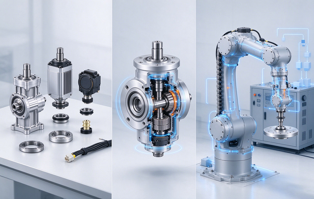
Deliverables and Functional Groups by Supply Level
Covering the mechanically complete elements of a drive train, the parts level spans strain wave reducers, cross roller bearings, and planetary reducers. The strain wave gear series covers reducer size 3 through size 58, with reduction ratios of 30:1 to 160:1 and outer diameters of 13 mm to 246 mm. Its frames span FSS, FSF, FSN, FSG, FHT, FHG, FHD, FHN, FBS-U, FBS-C, and Mini. A unit at this level converts speed and torque at a defined accuracy and backlash.
Around that stage the components level adds the motion hardware. A Laifual Drive joint module integrates a servo motor, a strain wave reducer, an absolute encoder, a servo drive, a brake, and torque sensing in one housing. Such a unit can be driven, commanded over a bus, and bolted in place. Because the groups are matched inside it, the buyer receives one axis accuracy figure instead of a stack of tolerances to combine. The encoder also retains position and multi-turn counts after a power loss, removing the homing routine a separate encoder would require.
Extending that content to a task defines the systems level. A robotic arm in the 3 kg to 20 kg payload class integrates reducers, motors, and encoders into a kinematic structure. An automation workstation combines that arm with conventional machine tools for flexible manufacturing and line upgrades. Here cycle time, line integration, and process knowledge govern the design more than any component parameter, so the deliverable is a motion system that starts and repeats.
Load, Accuracy, and Life Criteria by Level
Every parameter needs its operating point. Rated torque is the permissible continuous load torque at a rated input speed of 2000 r/min, so a size quoted at a higher speed carries less continuous torque. Average load torque Tav is the torque over a full duty cycle, computed from each phase’s torque and time share. It sets the frame size, since the selected size must offer a permissible average load torque at or above Tav. Average input speed Ni av and maximum input speed Ni max are checked against the catalog range for the ratio and frame.
Backlash is specified by series at up to 60, 30, or 20 arc seconds, positioning accuracy at ±15 arc seconds, and design life at 10,000 to 15,000 hours. Developed from the double circular arc profile, the delta tooth profile is a multi-segment variable curvature arc form. It raises load capacity by 15% to 30% and lowers temperature rise by 8 to 10 °C. That profile also reduces the contact area affected by tooth flank fatigue pitting by more than 30%, and it supports continuous running life beyond 15,000 hours.
Two further checks enter at the components level, both carried by the supplier. Unit type modules contain an integrated cross roller bearing, so maximum moment load, bearing life, and static safety factor are verified at the worst posture of the machine. Motor insulation is class F at 155 °C, and the enclosure reaches IP67, with black oxide treatment on T type joints and selected precision bearings.
At the systems level the criteria change in character: cycle time, task repeatability, and integration effort at the production line govern the design, while component parameters are accepted as inputs. Verification evidence shifts the same way: a data sheet at the parts level, matched-unit test data at the components level, and process validation at the systems level.
Verified Values by Supply Level
| Supply level | Deliverable | Interfaces owned by the supplier | Work retained by the buyer | Typical team stage |
|---|---|---|---|---|
| Parts | Strain wave reducer, cross roller bearing, planetary reducer | Mechanical mounting interface and rated data | Motor, encoder, sealing, lubrication, control loop | Transmission design capability in-house, or an established platform |
| Components | Joint module with motor, encoder, drive, brake, force sensing | Shaft alignment, encoder mounting, commutation, protocol configuration | Mounting, bus setup, motion profile, safety logic | Kinematics proven, build and ship schedule under pressure |
| Systems | Robotic arm or automation workstation | Motion architecture, kinematic layout, process integration | Application requirement and final machine acceptance | New kinematics, unusual envelope, or a first robot line |
| Level | Specification item | Verified value |
|---|---|---|
| Parts | Reducer size range | Size 3 to size 58 |
| Parts | Reduction ratio | 30:1 to 160:1 |
| Parts | Outer diameter | 13 mm to 246 mm |
| Parts | Positioning accuracy | ±15 arc seconds |
| Parts | Backlash by series | Up to 60, 30, or 20 arc seconds |
| Parts | Design life | 10,000 to 15,000 hours |
| Components | Module outer diameter | 40 mm to 190 mm, continuous |
| Components | Drive variants | 48 V DC low voltage, 220 V AC high voltage |
| Components | Module models | L70I to L170I on DC, M80D to M170D on AC |
| Components | Protocol set | BiSS-C, TAMAGAWA, CANopen, CAN FD, EtherCAT, Modbus |
| Components | Protection and winding class | IP67, class F at 155 °C |
| Systems | Arm payload class | 3 kg to 20 kg |
| Systems | Non-standard solution cycle | Approximately 2 weeks, samples at approximately 4 weeks |
Laifual Drive runs a 47,000 square meter plant with an R&D team of more than 100 people. Its joint research platforms run with Chongqing University, Zhejiang University of Technology, and Huazhong University of Science and Technology. The company counts more than 10 years in the field and more than one million harmonic reducers delivered. Its own smelting and flexspline forging lines reached a flexspline self-supply rate above 80% in 2025, and its heat treatment plant covers quenching, tempering, austempering, and vacuum processing. Flexspline, circular spline, and cross roller bearing are produced in-house, and self-developed gear shaping cut core part machining from 2 to 3 hours to under 15 minutes.
The same in-house chain extends to application engineering at the systems level. A non-standard design typically reaches a solution in about 2 weeks and a first sample in about 4 weeks, and the custom design service carries the load, life, and interface work a machine-specific envelope requires.
Selecting the Supply Level Axis by Axis
- Count the axes and engineering hours the team can commit before design freeze; where that capacity exists in-house, the parts level keeps the performance model under direct control.
- Identify which links of the chain are tightly coupled on the drawing. Where shaft alignment, encoder mounting, commutation, and sealing cannot be separated, the components level moves that block to one supplier; a robotic joint module is the reference form.
- Fix the reduction stage on duty cycle data instead of peak torque. Compute Tav, confirm it sits at or below the permissible average load torque of the candidate size, then check Ni av and Ni max against the rated input speed of 2000 r/min.
- Add the bearing check wherever the size is a unit type: maximum moment load, bearing life, and static safety factor at the worst posture of the machine.
- Compare the accuracy requirement with the specified classes before the ratio is frozen: backlash of up to 60, 30, or 20 arc seconds by series, positioning accuracy of ±15 arc seconds.
- Choose the drive variant and protocol version at the axis level. Use 48 V DC low voltage for distributed control along an arm, with 220 V AC high voltage for high power axes and large hollow shafts. Set the -C or -E version for CANopen or EtherCAT.
- Move to the systems level when the envelope, load path, or accuracy target falls outside every catalog shape. Define the bearing, structural parts, and interface geometry around the machine instead of adapting the machine to a catalog outline.
Installation, Commissioning, and Maintenance by Level
Installation and maintenance obligations follow the level of purchase. Sealing stays with the buyer at the parts level. The FHT-I, FHT-II, and FHT-V configurations specify oil seal and groove dimensions. Assembly requires sealing between the input fixed end and the circular spline, sealing between the output end and the circular spline, and grease filling the flexspline cavity. Before the joint enters a load path, the mounting pattern and flange tolerance are checked at the components level; at the systems level acceptance is a process measurement at the production line.
Three points are worth recording whatever level is bought.
- Record the protocol version and encoder parameters at commissioning: an absolute encoder keeps position and multi-turn counts across a power loss.
- Keep the duty cycle inside the envelope the selection procedure established: a joint that runs above its thermal operating point loses life before it loses accuracy.
- Keep the data sheet and the system specification in one document trail, so component limits stay visible when a system requirement changes late in a program.
A team building transmission know-how should buy at the parts level, while a team shipping machines should buy the level that removes its integration hours. Programs commonly move one level up after the first prototype.
Choosing the Right Supply Level
Choosing a level is a design decision taken axis by axis before quotations are compared, and the right level follows the engineering capacity a team holds. Parts supply leaves motor selection, feedback, sealing, and control loop design with the buyer. It delivers reducers from size 3 to size 58 at backlash of up to 60, 30, or 20 arc seconds.
Components supply closes the coupled block of alignment, commutation, and protocol configuration inside a matched unit, and returns an axis figure of ±15 arc seconds. A design team should therefore count the integration hours it can absorb before design freeze, and treat the next level up as the route that keeps a program on schedule when loads or requirements change.