Harmonic Reducers, Joint Modules, Bearings and Planetary Gearboxes in One Transmission Solution
Compare harmonic reducers, planetary gearboxes, cross roller bearings, and joint modules. Learn torque, backlash, and sizing rules for precision drives.
 October 06, 2026
 > Resources > Harmonic Reducers, Joint Modules, Bearings and Planetary Gearboxes in One Transmission Solution
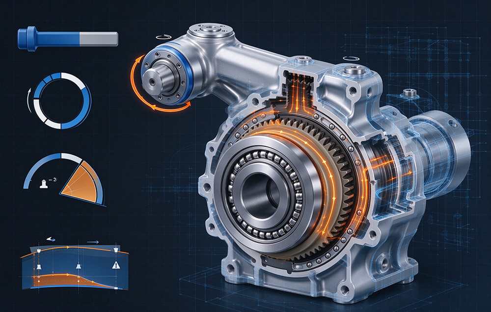
 A harmonic reducer is a strain wave gear set in which a thin-walled flexspline with two fewer teeth than the circular spline is deformed by an elliptical wave generator. Reduction is high in a shallow axial envelope. A planetary gearbox divides input torque among planet gears running between a sun gear and a ring gear, which suits high rigidity and heavy load duty better than a thin profile. Neither carries its own rotating part or sets the rotational accuracy of an axis; a precision bearing does.
Selecting a harmonic reducer and planetary gearbox is therefore a question about interfaces, because each element fixes a constraint the next inherits.
One material and process base also serves all four lines. Flexspline steel is melted and forged in-house, heat treatment covers quenching, tempering, austempering and vacuum treatment, and the flexspline, circular spline and cross roller bearing are produced internally. Explore our full product catalog or contact our technical support team for custom configuration.
Strain Wave Deflection, Planet Sharing and the Support Side
Strain wave gearing uses three parts. The wave generator is an elliptical ball bearing that deflects the flexspline into the shape of its outer race. Thin-walled and externally toothed, the flexspline is a cup that follows that deflection. Rigid and internally toothed, the circular spline carries two more teeth. Because the tooth counts differ by two, each input revolution rotates the output backward by two teeth, with about a third of the teeth in contact at once.
Two consequences follow for design. Torsional stiffness is load dependent and rises as more teeth engage, so the torque-rotation curve shows a low-stiffness region near zero torque. Thin walls that allow the deflection also allow a small elastic wind-up, so backlash and lost motion have to be read together.
A planetary gearbox uses a sun gear, three or more planet gears on a carrier, and a ring gear. Torque splits among the planets, lowering the load on each mesh while keeping the stage stiff and radially compact; its limits appear where very low backlash or a thin axial profile is required.
Support sits on a separate line. A cross roller bearing places cylindrical rollers at 90 degrees to one another in a single raceway. One bearing then carries radial, axial and moment load together, keeping the joint stack short. It also defines the rotational accuracy and the stiffness of the structure the reducer output sits on. A precise reducer on a loose bearing still yields an inaccurate axis, because an axis error budget is the sum of its parts. Integration moves that budget, since a joint module arrives with motor, reducer, encoder and drive already matched.
Family Coverage and the Interface Each Line Fixes
Size 3 to size 58 defines the standard harmonic range, with ratios of 30:1 to 160:1 and outside diameters of 13 mm to 246 mm. Several hundred SKUs cover the FSS, FSF, FSN, FSG, FHT, FHG, FHD, FHN, FBS-U, FBS-C and Mini families, alongside the FB series double circular spline arrangement.
A multi-segment, continuously variable curvature arc replaces the conventional double circular arc in the δ tooth profile. Load capacity rises by 15 to 30 percent, temperature rise falls by 8 to 10 °C, and continuous running life exceeds 15,000 hours.
Roughly 30 percent lighter than an equivalent standard unit, the FSN lightweight family holds rated torque, stiffness and transmission accuracy. Range details are on the strain wave gear series page.
Joint modules cover outside diameters from 40 mm to 190 mm without a gap: roughly size 8 at 40 mm, size 40 at 170 mm. The DC low voltage family runs on 48 V DC with the servo drive built in for humanoid robots, collaborative robots and distributed control. The AC high voltage family runs on 220 V AC with hollow shaft capability for high power industrial arms and CNC equipment. Payload classes run from 3 kg to 20 kg, protection reaches IP67, and the model series are listed on the joint modules page.
Precision bearings own the support side. High rigidity, high precision and a compact section come together in the cross roller bearing, which spans small frames to large non-standard bearings where structural design carries the load. Rotary tables and robot joints need both elements designed together, and one supplier allows stiffness and accuracy to be optimized as a set, as it does for planetary gearboxes and precision bearings.
Planetary gearboxes complete the matrix at the other end of the duty range, where high rigidity and heavy load dominate. Carrying both forms lets a machine builder choose the transmission type by operating condition, as the harmonic planetary gearbox guide sets out.
| Product line | Duty in the transmission chain | Interface it fixes | Where it stops being the right answer |
|---|---|---|---|
| Harmonic reducer | Reduction, backlash grade and torque density in a shallow envelope | Ratio, input shaft, output flange, output speed and resolution | Very high torque at moderate accuracy, where a planetary stage costs less per Nm |
| Planetary gearbox | High rigidity and heavy load duty, multi-stage ratio | Ratio distribution, housing stiffness, load path to the frame | Minimum backlash and thin axial profile requirements |
| Precision bearing | Carries radial, axial and moment load; sets rotational accuracy | Joint stiffness, moment load capability, output runout | Cannot substitute for the reduction stage or the encoder |
| Joint module | Pre-matched motor, reducer, encoder, drive, brake and sensing | Electrical interface, bus, calibration, enclosure rating | Builders who must own motor and drive selection themselves |
Torque, Backlash and Moment Load Definitions
Rated Torque and Its Input Speed Basis
Rated torque in the Laifual Drive catalogs is the permissible continuous load torque at a rated input speed of 2000 r/min. A torque figure quoted without an input speed cannot be compared across suppliers. Permissible average load torque is the ceiling that applies to the averaged duty, not the peak.
Average Load Torque and Input Speed Checks
Average load torque Tav is the output torque averaged over a duty cycle, weighted by time and by the torque and speed relationship of that cycle. Average input speed Ni av and maximum input speed Ni max are checked separately, since a drive can survive a peak speed it could not sustain as an average.
Backlash, Lost Motion and Hysteresis
Backlash is specified by series at ≤60, ≤30 or ≤20 arc seconds, measured at the output with the input held. Lost motion and hysteresis are larger, because they add the elastic deflection of the teeth, the flexspline wall and the bearing to the geometric play. Traced upward and back down, the torque-rotation loop encloses that difference.
Moment Load and Bearing Life Criteria
For unit type reducers, those with a built-in cross roller bearing, three further criteria apply: maximum moment load, bearing life and static safety factor. These are structural limits independent of the gear rating, so a reducer that meets its torque requirement can still fail when the arm applies a moment load beyond the bearing capacity.
Catalog Values Behind the Selection Envelope
Values below come from the Laifual Drive catalog.
| Harmonic Reducer Parameter | Verified Value |
|---|---|
| Size range | size 3 to size 58, full series |
| Reduction ratio | 30:1 to 160:1 |
| Outside diameter | 13 mm to 246 mm |
| Positioning accuracy | ±15 arc seconds |
| Backlash, by series | ≤60, ≤30 or ≤20 arc seconds |
| Design life | 10,000 to 15,000 hours |
| Rated torque definition | permissible continuous load torque at 2000 r/min rated input speed |
| δ profile, load capacity | 15 to 30 percent above the conventional double circular arc profile |
| δ profile, temperature rise | 8 to 10 °C lower |
| δ profile, fatigue pitting | more than 30 percent less tooth flank contact area affected |
| δ profile, continuous running life | more than 15,000 hours |
| Joint Module Parameter | Verified Value |
|---|---|
| Outside diameter coverage | 40 mm to 190 mm, continuous |
| Size mapping | 40 mm approximately size 8; 170 mm approximately size 40 |
| DC low voltage family | 48 V DC with built-in servo drive; L70I, L80I, L90I, L110I, L142I, L170I |
| AC high voltage family | 220 V AC with large hollow shaft capability; M80D, M90D, M110D, M142D, M170D |
| Robot arm payload classes | 3 kg to 20 kg |
| Protection | IP67 |
| Motor insulation | class F (155 °C) |
| Communication protocols | BiSS-C, TAMAGAWA, CANopen, CAN FD, EtherCAT, Modbus |
| Fieldbus versions, low voltage | -C for CANopen, -E for EtherCAT |
| Feedback | absolute encoder retaining position and multi-turn count after power loss |
From Duty Cycle to Frame Size and Ratio
Each step produces a number or decision the next step consumes.
- Define the duty: load torque and output speed against time for the full cycle, the required positioning accuracy, and the available envelope.
- Convert the cycle into criteria: compute average load torque Tav and average input speed Ni av, then identify peak torque and maximum input speed Ni max. Fluctuating loads must be reduced to equivalent averages first.
- Select the frame size so that the permissible average load torque covers Tav, with Ni av and Ni max inside the allowable input speeds.
- Choose the ratio between 30:1 and 160:1. A higher ratio raises output torque and axis resolution while lowering output speed, so verify the maximum output speed the motion profile requires.
- If the stage has a built-in cross roller bearing, add the structural checks: maximum moment load at the output flange, bearing life and static safety factor. This reducer must not be used as the structure of the joint.
- Decide the transmission form. Minimum envelope, low backlash and high positioning accuracy point to a harmonic reducer; high rigidity with heavy load and a tolerant backlash specification point to a planetary gearbox.
- Decide part or module. Builders who intend to own motor, encoder and drive selection should order reducer and bearing as parts. Where development hours bind, the joint module removes that work, with -C for CANopen or -E for EtherCAT.
- Close the integration boundary: mounting interface, sealing arrangement, grease fill quantity in the flexspline cavity, encoder protocol and safety logic. Where rotation accuracy decides the process result, verify the cross roller bearings selection in the same pass as the gear.
Sealing, Lubrication and Maintenance Practice
Sealing is specified by frame. FHT-I, FHT-II and FHT-V arrangements each define an oil seal and its groove dimensions. Assembly requires a seal between the input fixed end and the circular spline or flexspline, a seal between the output end and the circular spline, and a defined grease fill in the flexspline cavity.
Lubrication and temperature belong together. Against the earlier geometry, the δ profile reduces temperature rise by 8 to 10 °C. Continuous duty machinery such as production line handling or machine tool indexing should be checked against the average load torque criterion instead of peak values.
Environment sets the sealing specification: IP67 modules suit washdown and dusty cells, and black oxide treatment on joints and bearing components raises corrosion resistance where condensation or coolant mist is present.
Maintenance follows from the structure. Backlash drift on a strain wave axis usually reflects wear at the tooth mesh or a change at the mounting interface, with the drive electronics rarely at fault. Backlash measurement at the output therefore remains the most direct health indicator.
Matching the Four Lines to the Application
Four product lines do not become a solution until the interfaces between them are engineered. Ratio, backlash and torque density come from the harmonic reducer, while the planetary gearbox covers the heavy load and high rigidity duties a strain wave stage should not absorb. Moment load and rotational accuracy belong to the cross roller bearing, and the joint module closes that same chain around a motor, an encoder and a drive.
One rule follows from that split: strain wave gearing where backlash and envelope decide the result, a planetary stage where rigidity and load do. Checking rated torque at 2000 r/min input, permissible average load torque, input speed limits and the bearing moment load check holds an axis at its accuracy. That accuracy lasts for the full 10,000 to 15,000 hour design life.