
Joint Module Size Coverage from 40 mm to 190 mm
Understand how joint module frame sizes map to harmonic reducers from 40 mm to 190 mm OD, and follow the step-by-step engineering selection sequence.
 October 07, 2026
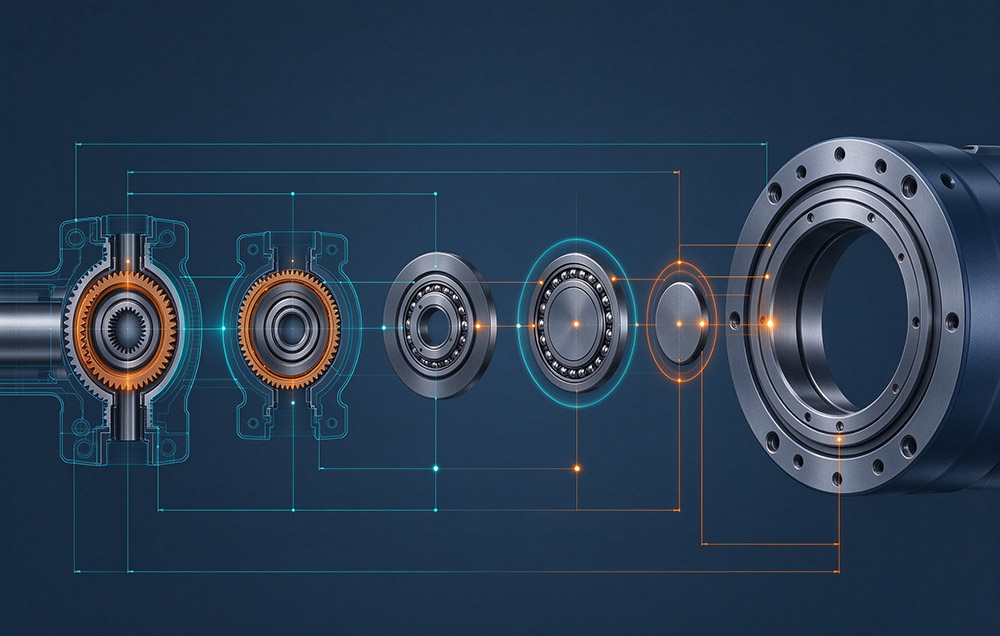
 > Joint Module Size Coverage from 40 mm to 190 mm
A joint module size is the frame class an integrated rotary actuator occupies in a supplier catalog. It is set by the outside diameter of the module, with the gear ratio inside playing no part. Laifual Drive covers that ladder continuously from 40 mm to 190 mm outside diameter. Behind the modules sits a harmonic reducer range from size 3 to size 58, with ratios of 30:1 to 160:1 and outside diameters of 13 mm to 246 mm.
No joint module stands alone as a catalog line. Each rung requires a reducer of the matching size, together with a motor, an encoder, a servo drive, a brake, and a cross roller bearing that fit the same envelope. One missing element removes that rung from the ladder, so coverage says more about a manufacturing chain than about a catalog listing.
How Frame Size Maps to Reducer Size
The industry divides harmonic reducers into housing sizes, while joint modules are quoted by outside diameter. Between the two conventions lies a direct correspondence: a 40 mm module outside diameter corresponds to roughly reducer size 8, and 170 mm to roughly size 40. An engineer holding a reducer drawing can read a module catalog directly, and what a module adds to a bare reducer is set out in what a joint module is.
A step in outside diameter moves the flexspline diameter, the circular spline tooth count at a given ratio, and the wave generator bearing. The cross roller bearing section, the rotor diameter, and the power stage of the integrated drive move with it. Where one of those parts exists only at a neighboring size, the rung stays nominal on paper.
The reducer ladder is the wider of the two, running from size 3 through size 58. Its outside diameters span 13 mm to 246 mm, with ratios of 30:1 to 160:1 across several hundred SKUs. The list covers the FSS, FSF, FSN, FSG, FHT cup and hat, FHG, FHD, FHN, FBS-U, FBS-C, and Mini families. Inside that band sits the continuous module ladder from 40 mm to 190 mm.
A gap in the ladder costs at two moments. During layout, the options are to redraw the structure around an available frame or to accept a non-standard design. During production, the non-standard path converts a catalog part into a project with its own schedule, quoted at about two weeks for a scheme and about four weeks for samples.
What Keeps Pace at Every Size Step
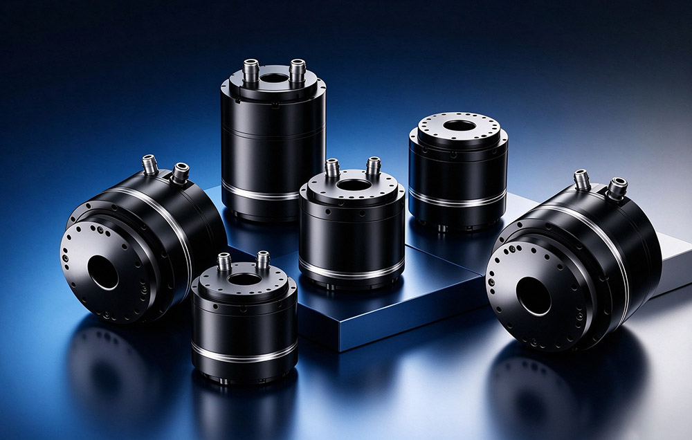
Two families carry the size range. The low-voltage DC family uses a 48 V supply and includes L40I, L52I, L60I, L70I, L80I, L90I, L110I, L142I, L170I, and L190I. The high-voltage AC family uses a 220 V supply and includes M70, M80, M90, M110, M142, M170, and M190. The available drive, feedback, brake, shaft, and communication configurations should be confirmed for each model. Payload classes and application suitability should likewise be checked against the relevant product data. Discover full technical sheets on our DC low voltage joint modules and AC high voltage joint modules.
| Item | Published Coverage |
|---|---|
| Joint module outside diameter | 40 mm to 190 mm across the range |
| Module size correspondence | 40 mm approximately size 8; 170 mm approximately size 40 (confirm against the selected product drawings) |
| DC low-voltage family | 48 V DC: L40I, L52I, L60I, L70I, L80I, L90I, L110I, L142I, L170I, L190I |
| AC high-voltage family | 220 V AC: M70, M80, M90, M110, M142, M170, M190 |
| Payload classes | Confirm payload suitability against the selected model and application duty |
| Harmonic reducer range behind the ladder | Size 3 to size 58; ratios 30:1 to 160:1; outside diameter 13 mm to 246 mm |
Behind the two families sits one component supply. Laifual Drive produces the flexspline, circular spline, and cross roller bearing internally, then extends that base to the motor, encoder, and drive at module level. The work runs on a 52,000 square meter site with more than 100 engineers in research and development. Gear cutting uses a self-developed skiving process that reduced machining time for core parts from two to three hours to under 15 minutes. Flexspline steel is melted and forged on dedicated lines, with flexspline self-supply above 80 percent in 2025. Heat treatment covers quenching, tempering, austempering, and vacuum treatment, and cumulative delivery stands at one million harmonic reducers.
The two ends of the ladder stress different skills. Small frames test machining accuracy at the micrometer scale, where wall thickness, roundness, and tooth form tolerances leave no room for correction. Large frames test structural design and the ability to machine large parts without distortion. A supplier holding one capability and not the other shows it as a gap in the middle of the catalog.
Rating Checks at Each Size Step
The Rated Point and Its Input Speed
Frame size does not by itself set torque. Rated torque in the Laifual Drive catalogs is the permissible continuous load torque at a rated input speed of 2,000 rpm, so a torque figure quoted without its input speed cannot be compared across catalogs.
Duty Averages and Speed Limits
Duty is judged on averages rather than peaks. Average load torque Tav is the output torque averaged over the duty cycle. It is weighted by time and by the torque and speed relationship of that cycle, then compared against the permissible average load torque of the frame at the intended ratio. Average input speed Ni av and maximum input speed Ni max are checked separately.
Backlash, Accuracy and Design Life
Backlash is specified by reducer series, with catalog grades such as ≤60, ≤30, or ≤20 arcseconds where applicable. Positioning accuracy and service life are system-level results that depend on the selected module, encoder, and drive configuration, load spectrum, speed, and operating conditions. Lost motion and hysteresis can exceed backlash because they also include elastic deflection in the teeth, flexspline, and bearing. Torsional stiffness in a strain wave gear stage is load-dependent; check the relevant model data rather than applying one accuracy or life figure to every module.
Structural Checks for Unit Type Frames
Three criteria apply to unit-type designs with an integrated cross roller bearing: maximum moment load, bearing life, and static safety factor. These structural limits are independent of the gear rating, so a frame that meets its torque requirement can still fail on a moment the bearing cannot carry. Protection, motor insulation, and feedback interfaces are model-dependent. The low-voltage DC family supports CANopen, CAN FD, EtherCAT, and Modbus options; the high-voltage AC family uses BiSS-C and TAMAGAWA interfaces as specified for the relevant products. Confirm encoder multi-turn retention and any dual-loop control capability for the complete selected system.
Tooth Form and Load Capacity
The δ tooth profile is a tooth-form design intended to improve meshing characteristics. Any claimed increase in load capacity, reduction in temperature rise, or improvement in pitting resistance should be tied to product-specific test conditions and verified technical data. A frame step changes the size of the parts that carry load, while tooth form affects how the load is distributed across the meshing teeth.
Published Size and Rating Data
The published figures below define the envelope for selection.
| Parameter | Verified Value |
|---|---|
| Joint module outside-diameter coverage | 40 mm to 190 mm across the range |
| Harmonic reducer sizes | Size 3 to size 58 |
| Reduction ratio | 30:1 to 160:1; verify availability by model and series |
| Reducer outside diameter | 13 mm to 246 mm |
| Rated torque definition | Permissible continuous load torque at 2,000 rpm input, subject to the applicable catalog definition |
| Positioning accuracy | Confirm against the selected module and complete control configuration |
| Backlash, by series | Catalog grades may include ≤60, ≤30, or ≤20 arcseconds; confirm the specified series |
| Design life | Calculated/qualified life depends on model, load spectrum, speed, and operating conditions |
| Protection and insulation | Confirm IP rating and motor-insulation class for the selected model |
| Feedback and bus protocols | DC low-voltage family: CANopen, CAN FD, EtherCAT, and Modbus; AC high-voltage family: BiSS-C and TAMAGAWA |
Selection Sequence for a Frame Step
- 1
Read the envelope first: take the available space and the mounting interface from the released drawing, then shortlist frames whose outside diameter fits.
- 2
Compute the duty: derive Tav from the torque and speed profile of the axis over the complete cycle.
- 3
Check the rated point: compare Tav with the permissible average load torque of the frame at the intended ratio, defined at 2,000 rpm input.
- 4
Check speeds separately: verify Ni av against the duty and Ni max against the peak move.
- 5
Confirm the backlash grade and positioning-accuracy requirement against the specified reducer series and complete joint-module configuration; do not assume one positioning-accuracy value applies to every axis.
- 6
Check the bearing side: for unit type designs, verify maximum moment load, bearing life, and static safety factor.
- 7
Fix the electrical and control interface: confirm 48 V DC or 220 V AC, shaft configuration, brake, feedback type, available communication protocol, and driver arrangement for the selected model.
- 8
Escalate one frame only when a criterion fails, since a frame step answers a failed check rather than a layout precaution.
| Property | Behavior When the Design Steps Up One Frame |
|---|---|
| Outside diameter and mounting envelope | Changes with frame size; re-check the surrounding structure and neighboring joint |
| Load capacity and torque at a given ratio | Generally changes with the design and size; verify ratings for the selected model |
| Cross roller bearing moment capacity | Verify against the bearing/module rating for the relevant load case |
| Current demand at 48 V DC | Depends on selected model and duty; size the drive and cabling accordingly |
| Reduction ratio set | Available ratios depend on series and model; verify the catalog |
| Backlash grade | Set by the reducer series and selected specification, not frame size alone |
| Communication and commissioning | Protocol options and commissioning requirements vary by model; verify before system integration |
Axis Roles, Oversizing and Installation
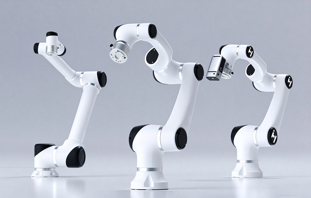
Axis count is what makes a continuous size range useful. A collaborative robot often carries six to seven rotary joints, while a humanoid robot can exceed twenty; shoulder, elbow, wrist, and waist positions differ widely in load and available space. Selecting models from one supplier can simplify supply-chain coordination, but mounting interfaces, communication options, and commissioning methods still need to be confirmed for each selected model. The axis roles themselves are described on the robotics applications page.
Installation practice scales with the frame. Sealing arrangements, including the input fixed end, output end, and grease fill in the flexspline cavity, must follow the relevant model drawing and assembly instructions. Where IP67 protection is specified, the complete sealing design and assembly process must meet that rating. T-type joints and some precision bearings receive black oxide treatment, a dense oxide film that can improve corrosion resistance. Where the standard range does not cover a requirement, the non-standard route is quoted at about two weeks for a scheme and about four weeks for samples. Axis-level selection is described in the robotic joint module overview.
Design Consequences of Continuous Size Coverage
Joint module size coverage at Laifual Drive spans outside diameters from 40 mm to 190 mm across the low-voltage DC and high-voltage AC families. The available reducer, motor, encoder, drive, brake, bearing, and interface configurations depend on the selected model. Confirm positioning accuracy, protection rating, and service-life requirements against the current catalog and application duty.
Selection runs from the available envelope to duty average, speed limits, and bearing checks, with a frame step reserved for a failed criterion. A team selecting from a broad size range can reduce structure revisions, but the mechanical interface, electrical configuration, and verification work still need to be checked against the released data for each chosen model.
Need Engineering Guidance for Joint Sizing?
Contact our application engineers for 3D envelope models, duty calculations, and custom actuator integration support.