
Strain Wave Gearing in Machine Tool Rotary Tables
Learn why strain wave gearing fits 4th and 5th axis CNC rotary tables. Discover key sizing steps for indexing accuracy, cutting torque, and moment loads.
 September 01, 2026
 > Strain Wave Gearing in Machine Tool Rotary Tables
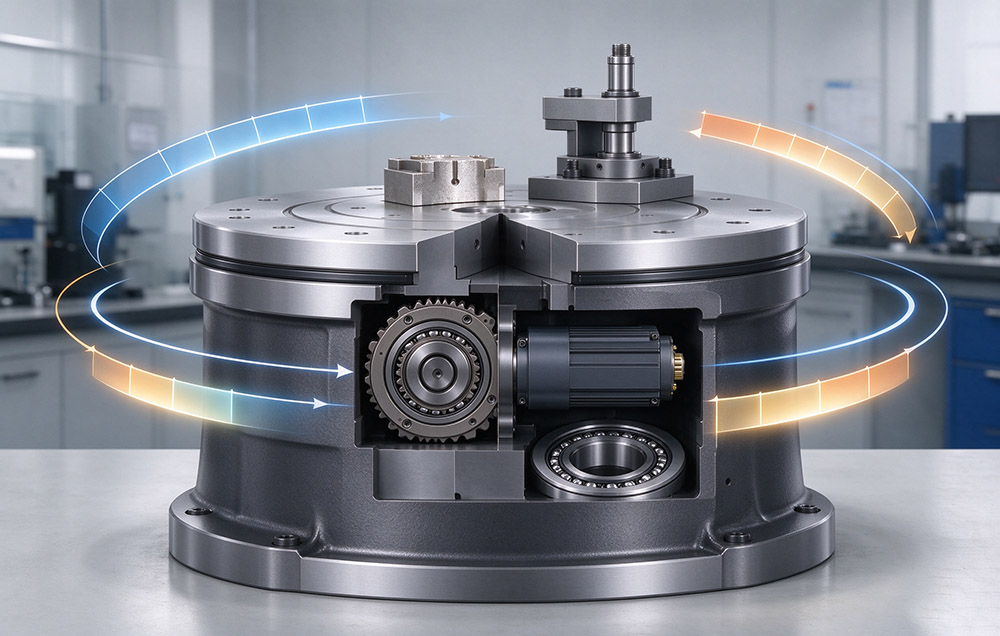
A rotary table drive turns the continuous rotation of a servo motor into an indexed angular position that holds while the tool is in cut. Top rotational speed matters less than the relationship between the commanded angle and the actual worktable angle. That relationship must stay the same across thousands of parts, with a cutting load applied and released on every tooth pass.
Strain wave gearing, also called a harmonic reducer, is widely used on the fourth and fifth axes of machining centers. One stage answers several requirements together: a high reduction ratio, low backlash through multi-tooth engagement, torsional stiffness that resists cutting torque, and smooth motion at low feed rates. Therefore, a rotary table harmonic reducer is specified against the indexing accuracy the machine has to hold, and peak motor torque sets only the outer envelope of that selection.
This article describes what a rotary table asks of its drive, how the strain wave mechanism answers those demands, and how one axis is selected and verified from its own load data.
Duty Conditions on a Machining Center Axis
A rotary table is loaded differently from a robot joint, where joint speed is high and the load is inertial. On a table, speed is low, the load is heavy and partly asymmetric, and an interrupted cut applies torque pulses at tooth-passing frequency. Table 1 lists the conditions that follow, and the consequence when each one is missed.
| Condition on the Axis | Origin | Consequence When It Is Not Met |
|---|---|---|
| High reduction ratio in one stage | The motor turns fast, the table indexes slowly and finely | A multi-stage train is needed, adding parts, cost, and lost motion |
| Low or near-zero backlash | The indexing command is a position, not a direction reversal | Commanded angle and actual angle differ, and the difference is transferred to the workpiece |
| Torsional stiffness | Cutting force passes from tool to workpiece to table as torque | Elastic windup between input and output deflects the workpiece during the cut |
| Load capacity for torque and moment | Workpiece and fixture weight, plus cutting reaction | Bearing and tooth flank overload, with shortened life |
| Smoothness at low speed | Fine feed and light finishing cuts | Stick-slip and uneven surface finish |
| Thermal stability | Continuous operation of the machine | Thermal growth inside the drive changes the angular relationship over a shift |
These first two rows are the reason strain wave gearing entered this application. Size and interface are decided by the remaining rows once the mechanism type is settled.
Why Strain Wave Gearing Fits the Indexing Axis
Indexing Accuracy and the Backlash Floor
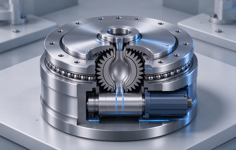
Across two diametrically opposite zones, the mechanism engages teeth at once, with many teeth in mesh together. Backlash comes from the geometry of that engagement, and there is no clearance to adjust. Standard units are available at ≤60, ≤30, or ≤20 arcseconds depending on series, and for a table indexed and clamped, that figure sets the floor on the repeatability quoted to the end user.
Single-Stage Reduction Without a Dead Band
A reduction ratio of 30:1 to 160:1 is available in one stage, which removes the intermediate stages that would otherwise contribute their own lost motion. Instead of sliding through a large tooth clearance, the flexspline deforms elastically. So there is no dead band at the start of motion, and the axis begins moving on the encoder counts that command it.
Torsional Stiffness Across the Cutting Load
The tooth mesh, the flexspline wall, and the bearing each contribute over a different torque range, so torsional stiffness is quoted as a curve rather than a single number. On a machine tool, the relevant region sits just above and below the cutting load. During the cut, the stiffness the axis sees differs from the slope at zero torque.
The δ tooth profile was developed to raise load capacity by 15 to 30 percent against the conventional double-circular-arc form. It lowers temperature rise by 8 to 10 °C and reduces the tooth flank area exposed to fatigue pitting by more than 30 percent. Continuous running life extends beyond 15,000 hours under the same comparison.
The gear tooth profile reaches the table only if the cutting process holds it. That is where precision gear shaping technology sets the tolerance that assembly inherits.
Components and Their Functions in a Table Drive
Four elements form the drive, and each has one job; Table 2 states them with the parameter that exposes a shortfall in service.
| Element | Function | Parameter That Exposes a Shortfall |
|---|---|---|
| Wave generator | Deflects the flexspline into an elliptical shape at input speed | Input speed limits, Ni av and Ni max |
| Flexspline | Thin-walled cup that carries the external teeth and deforms once per input revolution | Fatigue life and torsional stiffness at load |
| Circular spline | Internal toothed ring fixed to the housing or the output, which sets the ratio | Backlash grade and output concentricity |
| Cross roller bearing | Carries the combined radial, axial, and moment load at the output | Moment load rating, bearing life, and static safety factor |
On a unit-type reducer, the cross-roller bearing is integrated, so the table flange is supported directly by the reducer and no separate bearing pair is needed. That removes one interface and one contribution to lost motion, but it transfers the moment load check onto the reducer drawing, where the workpiece overhang has to be accounted for.
Parameter Definitions for Indexing Motion
Selection is only repeatable when the terms are defined the same way on both sides of the inquiry, so Table 3 fixes the definitions used here.
| Parameter | Definition | Unit |
|---|---|---|
| Rated torque | Permissible continuous load torque at a rated input speed of 2,000 rpm | N·m |
| Permissible average load torque | Upper bound for the average torque of the duty cycle, compared with Tav | N·m |
| Tav | Average load torque of the duty cycle, computed from its speed and torque segments | N·m |
| Ni av | Average input speed over the duty cycle | rpm |
| Ni max | Maximum input speed reached during the duty cycle | rpm |
| Backlash | Lost motion at the output with the input fixed, quoted by series | arcsec |
| Lost motion | Total torsional play including hysteresis under a defined torque cycle | arcmin |
| Repeatability | Spread of output position over repeated approaches to the same command | arcsec |
| Design life | Service interval at the specified load and speed conditions | hour |
Lost motion includes hysteresis, so it grows when the torque cycle is reversed, and it depends on the torque amplitude used to measure it. Design life is quoted at a specified average load and speed, so a unit that passes at the catalog duty can still fall short of the target hours if the real duty cycle is heavier. The step sequence used for selecting a harmonic reducer for CNC machines resolves both by working from the segment list of the process.
Selection and Verification for One Axis
What follows assumes the axis, motor, and reduction ratio have been proposed, and tests that proposal against the machine duty.
01
Build the duty segments: reduce the duty cycle to segments, each with a torque, a duration, and an input speed. An interrupted cut, a rapid index, and a dwell can be compared on that one basis.
02
Compute the average load torque Tav from the segments and compare it with the permissible average load torque of the candidate frame. This is the primary sizing check. Any unit that passes it is sized for the thermal and fatigue duty of the cycle, not for its peak.
03
Check the average input speed Ni av against the permissible value for continuous operation. Then check the maximum input speed Ni max against the limit for the unit. On an axis that is otherwise lightly loaded, a rapid index can set Ni max well above Ni av.
04
For a unit-type reducer, check the maximum moment load on the output flange against the cross-roller bearing rating. Confirm bearing life and static safety factor at that load. Workpiece overhang is the usual source of a moment load that the torque calculation never sees.
05
Check the accuracy grade against the tolerance on the part. Positioning accuracy of ±15 arcseconds and a backlash grade of ≤60, ≤30, or ≤20 arcseconds have to be read together with the machine error budget. The encoder and the clamping system belong in that budget.
06
Check the thermal path, because temperature rise inside the reducer adds to table and workpiece growth. A design life of 10,000 to 15,000 hours applies at the specified load and speed, not an arbitrary duty.
07
Confirm the interface, since shaft, flange, sealing, and lubrication provisions follow the mounting class in use. Changing them now is cheaper than changing them after the housing has been drawn.
Steps two and four carry most of the risk, because they use two different load descriptions of the same workpiece. Close to the table center, a heavy workpiece can pass the torque check and still exceed the bearing rating. A light workpiece held far out on a fixture can do the reverse, passing the bearing check while the torque duty defeats the unit.
Hollow Shaft Configurations and Routing
On a machine tool, the space behind the table is usually already committed to cables for a workpiece probe, hydraulic or pneumatic lines for the fixture, and coolant routing. A hollow-shaft reducer passes those services through the center of the axis. The hollow shaft FHT series provides that bore, and the largest hollow variants also appear in the AC high-voltage joint module range for higher-power industrial duty.
Two effects follow. A cable loop that has to articulate with the axis applies a varying side load and a varying torque to the table, and it wears at a rate that tracks the cycle count. A fixed internal route removes both. Lines routed outside the axis also occupy the same envelope as the drive and the clamping mechanism, so the housing grows in size and loses stiffness to make room for them.
Sealing and Lubrication Fixed with the Bore
Sealing and lubrication are fixed with the bore, since the flexspline cavity has to be filled with grease and the input and output ends sealed against the fixed housing. Seal and groove dimensions therefore follow the series variant, not a general figure. On a machine tool, the sealing requirement is set by the coolant and chip environment that surrounds the table. Mounting class is therefore chosen from that environment, not from the bore size.
Specifying Rotary Table Drives
A rotary table drive is bounded by the duty cycle, not by the motor rating. Four constraints do the bounding: the average load torque, the moment load on the output bearing, the accuracy and backlash grade, and the life at the specified speed. Strain wave gearing answers the first three structurally. It does so through a single-stage ratio of 30:1 to 160:1 and a backlash grade down to ≤20 arcseconds by series. An integrated cross-roller bearing then carries the table flange directly on unit-type reducers.
The catalog envelope covers the range of machines involved, from a small precision table to a large machining center. The strain wave gear series runs from size 3 to size 58 at outside diameters of 13 mm to 246 mm across several hundred SKUs. For heavier cutting, the high-torque series raises torque capacity against the standard range in the same envelope. The lightweight FSN series reduces mass by about 30 percent while holding rated torque, stiffness, and transmission accuracy.
For a designer, the practical conclusion is that a rotary table harmonic reducer should be specified from the segment list of the real process, not from a nominal torque figure. Compute Tav, check Ni av and Ni max, verify the moment load and bearing life at the output, and choose the backlash grade against the part tolerance. Machine tool applications of this kind are served from the same size range. Where an interface falls outside it, the correct starting point is the axis load data, not a larger catalog size.
Optimize Your 4th & 5th Axis Machine Tool Design
Contact our CNC engineering applications desk for duty cycle segmentation analysis, moment load verification, and 3D step model integration support.