
Transmission Requirements for Semiconductor Cleanrooms
Explore transmission requirements for semiconductor cleanroom robots: low particle emission, low-speed smoothness, hollow shaft routing, and zero backlash.
 September 03, 2026

 > Transmission Requirements for Semiconductor Cleanrooms
Each semiconductor cleanroom robot joint carries a few hundred grams of load, and it is nevertheless specified more tightly than a joint on a tonnage press. Wafer and panel handling arms move a thin, brittle, and expensive substrate between process stations. One stray particle, one visible vibration, or one lost position destroys the work in progress. In each of those joints, the transmission is therefore chosen against contamination, motion quality, and repeatability at once, not against load capacity alone.
The load side is small. One wafer carrier holds a few hundred grams of silicon, and a panel end effector holds a glass sheet whose mass is governed by area and thinness. Motor torque margin is generous, so rated torque almost never selects the drive. Three properties decide the design instead: behavior at very low speed, what the drive releases, and how steadily it holds position.
This article sets out the transmission requirements cleanroom duty places on robot joints. It covers wafer and panel transfer together with 3C precision assembly, and treats lubrication and surface treatment as decisions the duty forces. These criteria apply to any axis serving semiconductor and 3C applications, where the payload is light and the cost of a defect is high.
The Three Constraints That Set the Specification
Particle Emission from Inside the Enclosure
Particle emission dominates. Any cleanroom is classified by the number of particles above a stated size present in a volume of air. Every moving surface inside the process enclosure is a candidate source. Wear debris from tooth engagement, volatiles released by grease, and aging products from elastomeric seals all reach the substrate. Any sub-micron defect there is a failed die. Grease selection and surface finish therefore outrank the considerations that would decide the same selection on a machine tool axis.
Motion Quality at Low Input Speed
Motion quality is the second constraint. Each wafer rests on an end effector by friction or vacuum, so vibration transmitted through the joint can shift it or mark a patterned surface. The amplitude that matters is measured in microns at the substrate. It is largest at the low input speeds a pick-and-place move demands.
Repeatability Across Stations and Over the Design Life
Repeatability is the third. Every wafer passes through several stations in a fixed sequence, and each transfer must land inside the tolerance of the receiving fixture. Backlash and lost motion that vary with the direction of approach appear as placement error, which calibration cannot remove. Long-term stability is the fourth: the same accuracy is expected over a design life of 10,000 to 15,000 hours, which is a statement about wear rate and grease life.
| Cleanroom Constraint | Mechanism Inside the Drive | Measure Used | Consequence for Selection |
|---|---|---|---|
| Particle emission | Flank wear debris, grease volatiles, seal aging | Low-emission grease, cleanable finish | Lubrication outranks torque margin |
| Motion smoothness | Transmission error, mesh excitation | Vibration at the substrate | Multi-tooth mesh, low starting torque |
| Repeatability | Backlash, lost motion at the output | Positioning accuracy, backlash class | Zero-backlash gear set |
| Long-term stability | Flank wear, grease degradation | 10,000 to 15,000-hour design life | Low wear rate, reduced temperature rise |
| Routing | Cables, gas, and vacuum lines | Bore diameter per size | Hollow shaft output |
Why Strain Wave Gearing Suits Clean Environments
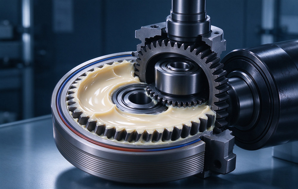
Strain wave gearing drives a thin-walled flexspline into mesh with a rigid circular spline through an elliptical wave generator. Torque is transmitted by elastic deformation of the flexspline, not by sliding contact between rigid bodies. That mechanism is described in how strain wave gears work, and four properties follow from that construction.
01
Three core parts, the flexspline, the circular spline, and the wave generator, make up the gear unit, so there are few sealing interfaces and few surfaces that can shed material.
02
The teeth engage over a broad arc rather than at a point, so the load on each tooth is small and the flank wear rate is low, which holds accuracy over a long duty cycle.
03
Starting torque is low because the mesh is preloaded by elastic deflection, so motion at the low speeds used for wafer alignment stays even.
04
The lubricant is a separate design variable, and a low-emission grease can be specified without changing the gear set.
The component set and the division of labor between parts are treated in harmonic drive components explained, and the same parts appear across the family of robotics components that a handler builder has to integrate.
| Component | Function | Relevance to a Cleanroom Axis |
|---|---|---|
| Flexspline | Thin-walled cup or hat deflected into mesh | Grease stays in the cavity at the flank |
| Circular spline | Rigid internal gear, two teeth more than the flexspline | High ratio in a compact sealed unit |
| Wave generator | Elliptical bearing deflecting the flexspline | Rolling contact, low starting torque |
| Cross roller bearing | Output bearing for radial, axial, and moment loads | Unit-type module hides the bearing from the clean space |
| Absolute encoder | Position and multi-turn count through a power cut | Restart without homing |
Parameter Definitions and Design Criteria
Rated torque is the permissible continuous load torque at a rated input speed of 2,000 rpm. An average duty torque is checked against it, not the peak torque of a single move. Backlash is quoted by series at 60, 30, or 20 arcseconds or less, referred to the output. Positioning accuracy over the module is ±15 arcseconds. Design life is 10,000 to 15,000 hours for the joint module range, assuming the axis runs inside its specified environment and grease remains at the tooth contact.
This delta tooth profile is a multi-segment variable-curvature continuous arc form developed from the conventional double circular arc. It raises load capacity by 15% to 30% and reduces temperature rise by 8 to 10 °C. Both figures matter in clean duty, because grease life and volatile release follow running temperature.
| Parameter | Value | Definition or Basis |
|---|---|---|
| Rated torque | Catalog value per size | Continuous load torque at 2,000 rpm input |
| Backlash | 60, 30, or 20 arcseconds or less | By series, at the output |
| Positioning accuracy | ±15 arcseconds | Repeatable output position |
| Design life | 10,000 to 15,000 hours | Grease retained at the flank |
| Load capacity gain | 15% to 30% | Delta profile against double circular arc |
| Temperature rise reduction | 8 to 10 °C | Delta profile, same duty |
| Fatigue pitting contact area | Reduced by more than 30% | Delta profile at the flank |
| Running-in life | Beyond 15,000 hours | Continuous running test |
| Protection class | IP67 | Dust tight, temporary immersion |
Hollow Routing and the Joint Architecture
A wafer handler usually carries more through the joint than torque. Cables for the end effector, pneumatic lines for a vacuum chuck, and, in some tools, a vacuum line for wafer clamping all cross the wrist. External routing is a particle source as well as a wear item. A hollow output keeps that bundle inside the joint, where conductors are shielded from the clean space.
The hat-type family is built with a large bore for exactly this reason, and the ultra-thin and lightweight hollow families keep a compact envelope with that bore. Where the axis is small and the payload sits at the lower end of the range, the Mini series covers compact joints in the same construction.
For builders who want gear, motor, encoder, and drive as one item, joint modules cover outside diameters from 40 mm to 190 mm continuously. A 48 V DC low-voltage branch carries an integrated servo drive for distributed and collaborative layouts. The 220 V AC high-voltage branch carries a large hollow shaft for high-power arms. A 40 mm outside diameter corresponds to roughly a size 8 unit, and 170 mm to a size 40 unit.
Lubrication and Surface Treatment Under Particle Control
Grease Volatiles and Seal Geometry
Lubrication is the largest controllable source of contamination inside a sealed drive. A grease releases a volatile fraction as it warms, and that fraction deposits on cold surfaces, which in a process tool means a wafer or a lens. Cleanroom duty therefore calls for a grease selected for low particle emission and a low volatile fraction, in a quantity that keeps the flank covered without surplus. Seal and groove geometry is specified per family (FHT-I, FHT-II, and FHT-V). Assembly requires sealing at the input fixed end and at the output against the circular spline, with a defined grease fill in the flexspline cavity.
Black Oxide on the Exposed Face
Surface treatment governs the outer face the clean space sees. Black oxide is an oxidation process that forms a dense oxide film on ferrous surfaces and raises resistance to rust, and it is applied to T-type joints and selected precision bearings. A treated surface holds an oil film better than a bare machined face and does not shed a coating.
IP67 Is Not a Cleanroom Rating
IP67 and cleanroom suitability are often treated as one requirement, but they answer different questions. IP67 concerns what can enter the enclosure from outside. The first digit, 6, means dust-tight, and the second digit, 7, means protection against the effects of temporary immersion in water under defined test conditions. It says nothing about what leaves the enclosure, and emission is what a cleanroom limits. A module can be dust-tight and still release grease volatiles or wear debris. A module with very low-emission grease can be unsuitable for a washdown cell.
| Question | IP67 Answers It | Cleanroom Requirement Answers It |
|---|---|---|
| Can particles cross the enclosure wall? | Yes, dust-tight | No, it limits what the drive releases |
| Can water cause damage? | Yes, temporary immersion | Not addressed |
| Does the grease release volatiles? | No | Yes, low volatile fraction required |
| Does the output bearing shed debris? | No | Yes, sealed unit-type bearing |
| Can the surface be wiped down? | Partly | Yes, a finish that does not shed a coating |
Checking an Axis Before Choosing a Size
The sequence below is the shortest route from a duty cycle to a defensible size, and it is the same for a wafer transfer axis and for a 3C assembly axis.
1
Reduce the duty cycle to an average load torque and compare it against the permissible average load torque of the candidate size. Peak torque during acceleration is a separate check.
2
Check average input speed Ni av against its limit, and maximum input speed Ni max during a fast move against its own limit, since a light axis is often run quickly.
3
On a unit-type module with an integrated cross-roller bearing, check the maximum moment load, the bearing life, and the static safety factor.
4
Fix the backlash class from the repeatability the receiving fixture allows. The tightest of the 60, 30, and 20 arcsecond classes is not always the right one.
5
Confirm bore diameter against the cable bundle and any gas line the joint has to pass, including the minimum bend radius of each conductor.
6
Check grease and surface treatment against the clean space, including volatile fraction and a finish that can be wiped.
7
Confirm encoder type and protocol against the controller, since an absolute encoder that retains multi-turn count through a power interruption removes a homing move per restart.
Specifying Drives for Cleanroom Handlers
The transmission requirements of a semiconductor cleanroom reduce to a short list. They are low emission, even motion at very low speed, repeatable position at the output, and stable accuracy over a 10,000 to 15,000-hour design life. Load capacity is not the binding constraint on a wafer or panel handling axis. Such a gear set with three core parts, a multi-tooth mesh, and low starting torque meets the duty without oversizing the motor. That specification work lies in lubrication, surface treatment, and the checks that follow from them.
Apply the procedure above in order, with average load torque, the two input speed limits, and the output bearing moment load settled before grease is chosen. Treating IP67 protection and cleanroom suitability as separate statements prevents the common error of assuming that a sealed module is a clean module. A drive specified that way holds its position for the life of the tool, not for the life of the first maintenance interval.
Configure Cleanroom & Vacuum-Compatible Actuators
Contact our semiconductor engineering team for low-outgassing grease selection, cleanroom particle test reports, and custom hollow-shaft robot joint models.